6
CHAPTER 1 - INSTALLATION
1.1 Inspection
l Inspect the inverter for any damage that may have occurred during shipping.
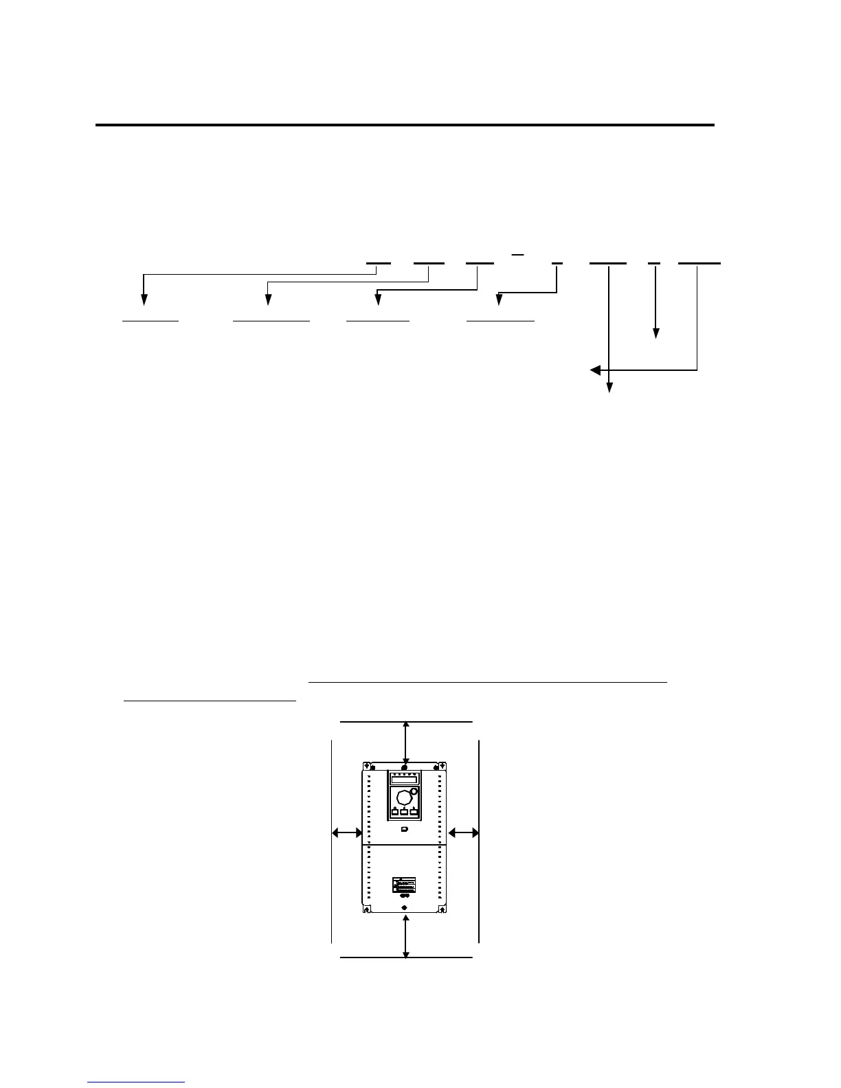
l Check the nameplate on the inverter. Verify the inverter unit is the correct one for the application. The numbering
system for the inverter is as shown below.
LG Inverter Motor Capacity Series Name Input Voltage
008: 1 HP 075: 10 HP 2: 200 ~ 230V (±10%) (50/60Hz)
015: 2 HP 110: 15 HP 4: 380 ~ 460V (±10%) (50/60Hz) UL Listed
022: 3 HP 150: 20 HP 4: 380 ~ 480V(±10%) (50/60Hz)
037: 5 HP 185: 25 HP
055: 7.5 HP 220: 30 HP N: Without Keypad
O/E: UL Open/Enclosed Type 1
DB: Built-in DB Unit
1.2 Environmental Conditions
l Verify ambient condition for the mounting location.
- Ambient temperature should not be below 14ºF (-10ºC) or exceed 104ºF (40ºC).
- Relative humidity should be less than 90% (non-condensing).
- Altitude should be below 3,300ft (1,000m).
l Do not mount the inverter in direct sunlight and isolate it from excessive vibration.
l If the inverter is going to be installed in an environment with high probability of penetration of dust, it must be
located inside watertight electrical boxes, in order to get the suitable IP degree.
1.3 Mounting
l The inverter must be mounted vertically with sufficient horizontal and vertical space between adjacent equipment
(A= Over 100mm, B= Over 50mm). However, A= Over 500mm and B= 200mm should be obtained for
inverters with 40Hp and above.
iS5
VARIABLE FREQUENCY DRIVE
Risk of Injury or Electric Shock
Risk of Electric Shock
Risk of Electric Shock
WARNING
EXT
RUN
ESC
SHIFT
FU2FU1DRV
ENT
PROG
RESET
STOP
LE-200
I/O
B
 Loading...