23
CHAPTER 2 - OPERATION
The iS5 series inverter has seven parameter groups separated according to their applications as indicated in the
following table.
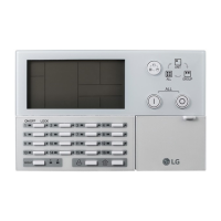
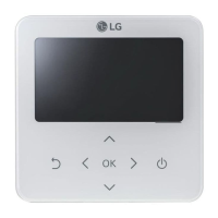
The iS5 series inverter provides two kinds of keypad. One is of 32-character alphanumeric LCD keypad and the other
is of 7-Segment LED keypad.
2.1 Parameter Groups
Parameter
Group
LCD Keypad
(Upper left Corner)
(LED is lit)
Description
Drive Group DRV ‘DRV’ LED
Command Frequency, Accel/Decel Time etc.
Basic Parameters
Function 1 Group FU1 ‘FU1’ LED
Max. Frequency, Amount of Torque Boost etc.
Basic Related Parameters
Function 2 Group FU2 ‘FU2’ LED
Frequency Jumps, Max./Min. Frequency Limit etc.
Basic Application Related Parameters
Input / Output
Group
I/O ‘I/O’ LED
Multi-Function Terminal Setting, Auto Operation etc.
Parameters needed for Sequence Operation
Sub-Board Group EXT ‘EXT’ LED Displayed when Sub-Board is Installed.
Option Group COM ‘I/O’ + ‘EXT ’ LED Displayed when Option Board is Installed.
Application Group
APP
‘FU2’ + ‘I/O’ + ‘EXT ’
LED
Traverse, MMC (Multi-Motor Control), Draw etc.
Application Related Parameters
Refer to the function descriptions in chapter 6 for detailed description of each group.
Morek IT OÜ, Rauna 24, 76506 Saue Harjumaa, Estonia. www.morek.eu Tel. +372 604 1423 Fax +372 604 1447 morek@morek.eu
 Loading...