Chapter 7 - Options
172
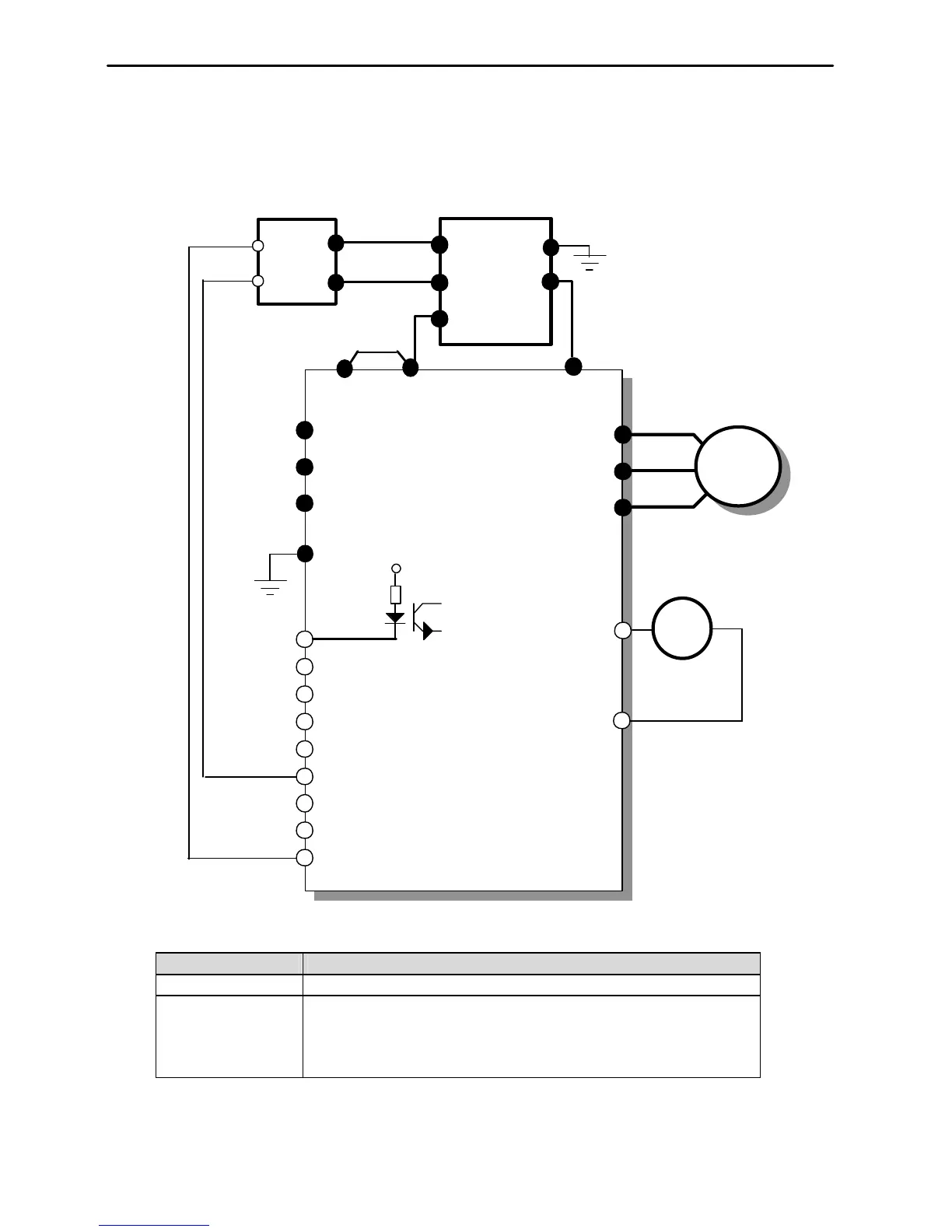
• DB Resistor/Unit wiring for 15-100 HP Inverter
DB resistor terminal Terminal description
B1, B2 Connect the DB Resistor to DBU terminal P/B1, B2.
TH1, TH2
Thermal sensors provided with the DB resistor.
P1 is ON (TH1-TH2 Shorted) at normal (ambient temp) and P1 is OFF (TH1-TH2
Open) at overheated status. Connect the thermal sensor to one of the multi-function
input (P1, P2 or P3, I/O 12-14 setting: Ext Trip-B).
* For DBU, refer to 7.7 DB Unit.
IM
Max distance between N&N: 5m
Wires should be Twisted.
Multi-function input terminal
(I/O-12 Setting: Ext Trip-B)
P& P2: 5m
P
Morek IT OÜ, Rauna 24, 76506 Saue Harjumaa, Estonia. www.morek.eu Tel. +372 604 1423 Fax +372 604 1447 morek@morek.eu
 Loading...