EasyManua.ls Logo

Lifetime 1044 User Manual

Lifetime 1044
76 pages
To Next Page IconTo Next Page
Page #1 background imageLoading...
Page #1 background image
1
TOOLS AND PARTS REQUIRED (NOT INCLUDED) TABLE OF CONTENTS
Pour le français, voir la page 2. Para el español, ver la página 3.
ASSEMBLY INSTRUCTIONS
MODEL 1044
SAVE THIS INSTRUCTION IN THE EVENT THE MANUFACTURER MUST TO BE CON-
TACTED TO OBTAIN REPLACEMENT PARTS.
CONTACT LIFETIME CUSTOMER SERVICE:
Dial 1-800-225-3865
7:00 am–5:00 pm (M–F) MST
and 9:00 am–1:00 pm (Saturday) MST
QUESTIONS?
MODEL# AND PRODUCT ID
(both are needed when contacting us)
Model Number: 1044
Product ID:
For Customer Service in Mainland Europe and the
United Kingdom,
E-mail: cs@lifetimeproducts.eu
Live Chat: www.lifetime.com/customerservice
(click on the “LIVE CHAT” tab)
QUICK ADJUST
®
CONVERSION KIT
BEFORE ASSEMBLY:
Before starting, decide where to mount the system: to a pole or to a wall. A mounting kit
is required for roof mounts and is available through our customer service department
(see page 11)
• At least 2 people recommended for setup
Icon Legend..................................................................4
Warnings & Notices......................................................5
Pole-Mount Assembly...................................................6
Wall-Mount Assembly.................................................15
Impact
®
Combo Assembly...........................................22
Fusion
®
Combo Assembly............................................31
Parts Identifi er..........................................................i–iv
Steel-Framed Combo Assembly.................................41
Pole Installation..........................................................60
Wall Installation..........................................................62
Adjustment of the Quick Adjust
®
...............................64
Maintenance............................................................65
Warning Sticker..........................................................66
Registration...............................................68
Warranty....................................................69
(2)
1/2" (≈13 mm)
(1)
3/8" (≈10 mm)
(2)
7/16" (≈11 mm)
Rim, backboard and net sold separately.
(2)
9/16" (≈14 mm)
(2)
3/4" (≈19 mm)
Or
(1)
2" x 4" x 20" (≈5 x 10 x 51 cm) Board
(2)
3.5" x 105"–3.5" x 112"
(≈8,9 x 266,7 cm–8,9 x 284,5) Pole
Question and Answer IconNeed help?

Do you have a question about the Lifetime 1044 and is the answer not in the manual?

Lifetime 1044 Specifications

General IconGeneral
BrandLifetime
Model1044
CategorySports & Outdoors
LanguageEnglish

Summary

Icon Legend

Special Heed Indicator

Indicates special attention is needed when reading.

Part Usage Indicator

Indicates which parts are required for a specific assembly section.

Hardware Usage Indicator

Indicates which hardware is required for a specific assembly section.

Tool Usage Indicator

Indicates which tools are required for a specific assembly section.

Drill Usage Indicator

Indicates whether to use or not use an electric drill for a specific step.

Centerlock Nut Indicator

Highlights the use of a centerlock nut for secure tightening.

Safety Warnings and Notices

General Warning Statement

Failure to follow warnings may cause serious injury, property damage, and void warranty.

Player Safety Responsibility

Owners must ensure players know and follow rules for safe system operation.

Assembly Safety Instruction

Follow instructions carefully during assembly to ensure safety.

Ladder Safety During Assembly

Use extreme caution when using a ladder for assembly steps.

Recommended Personnel for Assembly

Recommends two capable adults for safe and proper assembly.

Brick Wall Mounting Caution

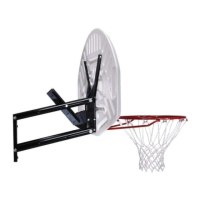
Brick walls may not be sturdy; secure mounting through brick and into studs is critical.

Pole Mount Assembly

Pole Mounting Height and Orientation

Set pole height at 8'1" and orient mounting tube correctly.

Pole Height Clearance Check

Verify pole height to prevent Quick Adjust mechanism interference.

Height Stop Installation for Pole Mount

Install height stop hardware to prevent Quick Adjust hitting wall.

Mounting Tube Cap Installation

Insert the cap (ALM) into the mounting tube (FKE).

Attaching Brackets and U-Bolts

Secure saddle brackets with hardware and attach U-bolts.

Sliding Assembly Without Height Stop

Slide assembly onto pole to 8'1" height without using height stop.

Sliding Assembly With Height Stop

Slide assembly onto pole to 8'6" height using height stop.

Wall Mount Assembly

Wall Height Clearance Check

Verify wall height to prevent Quick Adjust II mechanism interference.

Height Stop Installation for Wall Mount

Install height stop hardware to prevent Quick Adjust hitting wall.

Mounting Backboard with Wood Blocks

Attach 2x4 boards to wall studs at specific heights as template.

Installing Mounting Tube Cap and Wall Brackets

Insert cap into mounting tube and attach wall brackets securely.

Securing Brackets to Backboard

Secure wall mounting brackets to backboard using lag screws.

Impact Combo Assembly

U-Bolt and Inner Guard Setup

Slide U-bolt through brackets; fold inner guard and secure brackets.

Rim Support Channel and U-Bolt Attachment

Set rim support channel, secure U-bolt ends through backboard and rim.

Impact Backboard and Rim Hardware Attachment

Attach rim to backboard using bolts, nuts, and channel.

Attaching Backboard Brackets to Backboard

Bend brackets outward, align holes, secure with bolts and nuts.

Outer Guard and Dunk Latch Installation

Fold outer guard and set dunk latch into it.

Dunk Latch and Lower Extension Arm Installation

Slide dunk latch, attach lower extension arms with hardware.

Upper Extension Arm Installation

Attach upper extension arms to brackets and Quick Adjust mechanism.

Fusion Combo Assembly

U-Bolt and Inner Guard Setup

Slide U-bolt through brackets; fold inner guard and secure brackets.

Rim Assembly Hardware Attachment

Attach rim hardware using bolts, washers, and T-nuts.

Attaching Backboard Brackets and Jam Nuts

Attach brackets to rim assembly, thread jam nuts onto U-bolt ends.

Spring and Retainer Plate Installation

Slide compression springs and retainer plate over U-bolt ends.

Securing Retainer Plate and Bending Brackets

Secure retainer plate with nuts; bend backboard brackets outward.

Attaching Backboard Brackets and Outer Guard

Secure backboard brackets with screws; fold outer guard and set dunk latch.

Quick Adjust Mechanism and Guard Placement

Slide Quick Adjust mechanism between guards; align holes.

Attaching Extension Arms

Secure extension arms to backboard brackets and Quick Adjust.

Steel-Frame Combo Assembly

Metal Frame Backboard and Rim Types

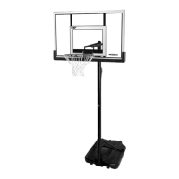
Identify metal frame backboard and rim types (Slam-it®, Slam-it® Pro).

Pivot Assembly and Bolt Installation

Assemble pivot, insert bolts through rim and housing.

Push Nut and Finger Guard Installation

Press push nuts onto axle; slide finger guards over bolts.

U-Bolt and Inner Guard Attachment

Slide U-bolt through brackets; fold inner guard and secure brackets.

Extension Arm Attachment to Backboard Bracket

Attach extension arms to backboard bracket with spacer and bolt.

Securing Extension Arm with Spacer and Nut

Slide spacer and extension arm onto bolt; secure with nut.

Attaching Remaining Extension Arms

Attach remaining arms with larger/smaller bolts and nuts.

Backboard Film Removal and Frame Pad Installation

Peel protective film from backboard; install center frame pad.

Corner Frame Pad Installation

Secure left and right corner frame pads to the frame.

Pole Installation

Mounting Backboards to Pole Tube

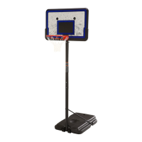
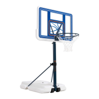
Mount backboards to pole tube using spacers and bolts.

Wall Installation

Mounting Backboards to Wall

Mount backboards to wall using spacers and bolts.

Adjusting the Quick Adjust System

Raising and Lowering the Goal

Use a broomstick to adjust the rim height up or down.

Safety Precautions During Adjustment

Keep hands away from moving parts, use caution, wear mouth guard.

System Maintenance

Regular System Inspection

Check for loose hardware, wear, and corrosion; take preventive measures.

Replacing Worn or Damaged Parts

Replace parts showing excessive wear or damage; contact customer service.

Warning Sticker Information

Critical Warnings and Usage Guidelines

Follow warnings for safety; avoid misuse, keep hands clear of moving parts.

Product Registration

Registering Your Product Online

Register product online for feedback, notifications, and recall information.

Product Warranty Information

5-Year Limited Factory Warranty

Warranty covers defects in material/workmanship for five years; excludes misuse and accidents.

Warranty Claim Procedure

Submit claims in writing with sales receipt and photos of damaged parts.

Register Product for Service

Register product online or by phone for faster customer service.

Related product manuals