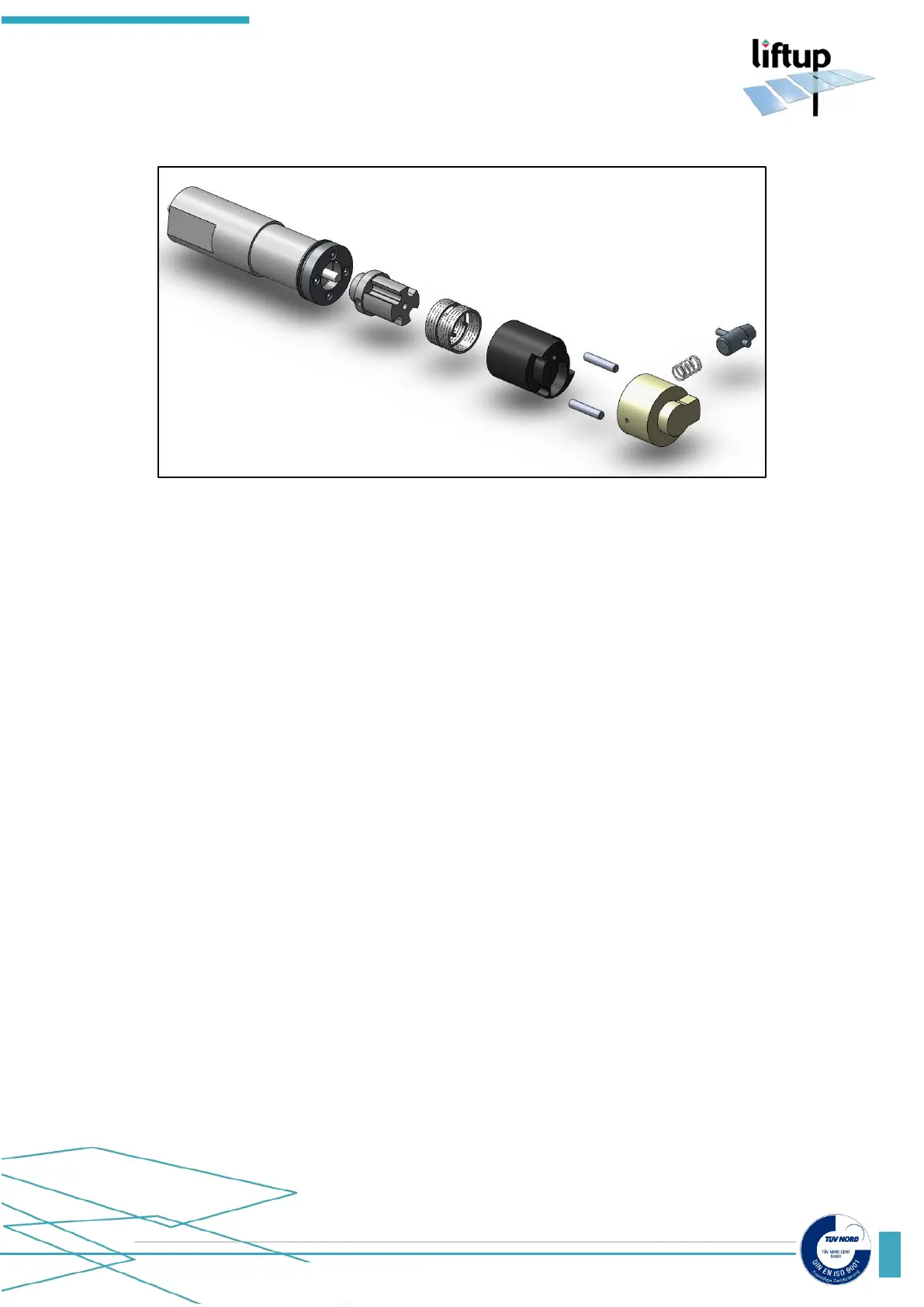
When assembling the lock unit:
E. Push the motor in by using the long M5 screw. Be careful that the cable will not be squeezed
between motor and ramp pipe. Remove the M5 screw.
F. Assemble the lock assembly, holding in the lock pawl at the same time. Turn the lock
assembly inside the tube until it fits.
G. Fasten the lock assembly to the side frame (A). The lock pawl should point towards the
micro switch.
Adjust the micro switch to be activated when the lock pawl is out, and do NOT activate the
switch, when the lock pawl is in the pipe.