Page 18 / 107 Section 4. Electrical connections
4. Electrical connections
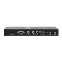
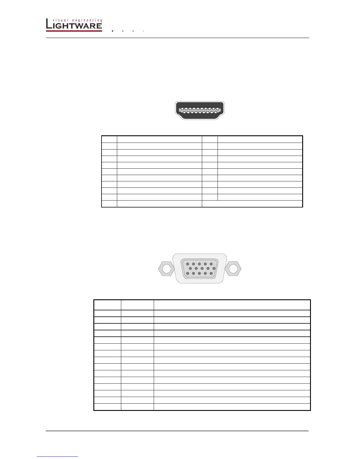
4.1. HDMI Input
UMX-OPT-TX150R provides standard 19 pole HDMI connector for HDMI input. Always
use high quality HDMI cable for connecting sources and displays.
HDMI Type A receptacle
Table 4-1. HDMI connector pin assignments
4.2. VGA Input
UMX-OPT-TX150R provides standard 15 pole D-SUB female connector for VGA input.
Always use high quality VGA cable for connecting sources and displays.
D-SUB 15 pole female connector (DE15F)
Red Video (75 ohm, 0.7 V p-p)
Green Video (75 ohm, 0.7 V p-p)
Blue Video (75 ohm, 0.7 V p-p)
Monitor ID Bit (Not used, internally connected to Pin 5)
Red Ground (Internally connected to Pin 5)
Green Ground (Internally connected to Pin 5)
Blue Ground (Internally connected to Pin 5)
Optional +5V output from graphics card
Sync Ground (Internally connected to Pin 5)
Monitor ID Bit 0 (Not used, internally connected to Pin 5)
I
2
C bidirectional data line
Vertical Sync which works also as data clock
Table 4-2. D-sub connector pin assignment for standard VGA