Service Training
Section 4.9
Page 5
12.05
4.9.1.4 CHECKING AND SETTING VALVE CLEARANCE
The valve clearance is to be checked and adjusted only with the engine cold.
- Remove valve cover.
- Turn the engine with screwdriver through open-
ing in the middle housing on toothed flywheel ring
until the valves on the 6
th
cylinder overlap.
In this position, check the valve clearance of the
first cylinder and adjust if necessary.
- Turn the flywheel further until the valves of the 2
nd
cylinder overlap.
Check the valves on the 5
th
cylinder and adjust if
necessary.
- Turn the flywheel further until the valves of the 4
th
cylinder overlap.
Check the valves on the 3
rd
cylinder and adjust if
necessary.
- Turn the flywheel further until the valves of the 1
st
cylinder overlap.
Check the valves on the 6
th
cylinder and adjust if
necessary.
- Turn the flywheel further until the valves of the 5
th
cylinder overlap.
Check the valves on the 2
nd
cylinder and adjust if necessary.
- Turn the flywheel further until the valves of the 3
rd
cylinder overlap.
Check the valves on the 4
th
cylinder and adjust if necessary.
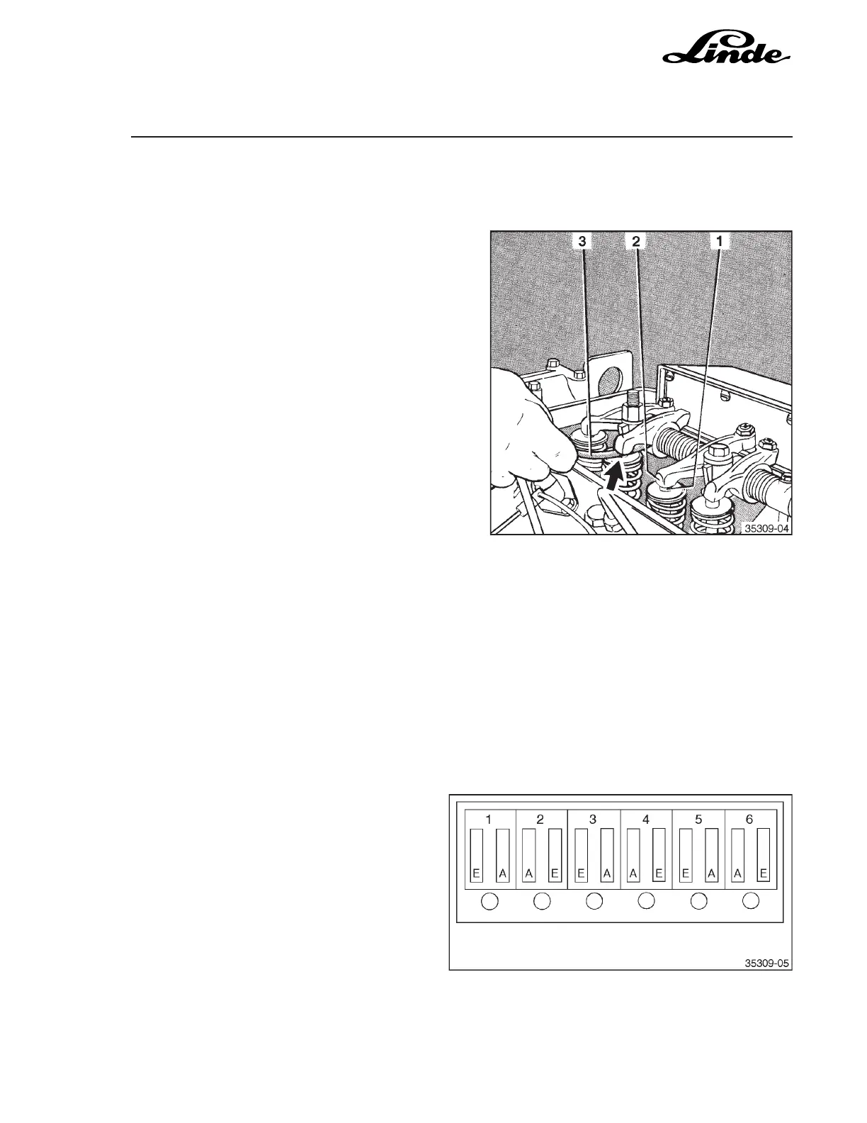
- Check the valve clearance between valve (1) and valve lifter (2) with a feeler gauge (3).
Target value, cold valve clearance:
Inlet valve 0.20 mm
Outlet valve 0.45 mm
The position of the inlet and outlet valves are
shown in the diagram.
E = inlet valve
A = outlet valve
NOTE: The 1
st
cylinder is on the water
pump side.