Service Training
Page 4.2
Section 3
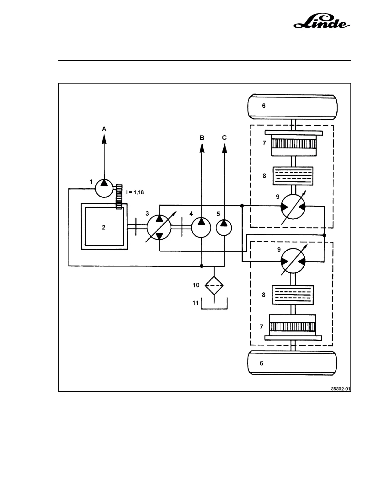
4.2.1.1 SCHEMATIC DIAGRAM OF THE DRIVE
1 Gear pump, 23 cc, due to transmission ration
1 engine revolution = 27 cc
2 Engine KHD BFM 6 1012 E
3 Axial piston pump BPV 100 S
4 Axial piston pump MPF 55 S
5 Gear pump, 27 cc
6 Traction wheels
7 Planetary hub reduction gearbox i = 17.45
8 Disc brake
9 Axial piston motor HMV 105 S
10 Suction filter
11 Oil tank
A Feed
B Working hydraulics
C Steering hydraulics