Page 3-1
MPS Motor Protection System Rev. 6-F-022117
System Wiring
3. SYSTEM WIRING
3.1 GENERAL
A typical connection diagram is shown in Fig. 3.2. The
MPS-CTU provides the 24-Vdc supply for the peripheral
modules and it communicates with them using an RS-485
interface. The total length of the I/O communication
system must be less than 1.2 km (4,000’). I/O
communications addressing supports up to three modules
of each type; however, the power supply in the MPS-CTU
will not support more than three I/O modules. An
external 24-Vdc power supply is required if more than
three modules are used.
The MPS-CTU voltage inputs can be directly
connected to a system with line-to-line voltages up to
600 Vac. PT's are required for system voltages higher
than 600 Vac. Input resistance of the voltage inputs is
3.4 MΩ.
NOTE: The current and voltage inputs must be phase
sequenced A-B-C with correct polarity observed.
START1, START2, and STOP starter-control
commands can be issued through the digital inputs, the
network interface, or the MPS-OPI. Start, stop, and
interlock contacts can be wired to any of the
programmable digital inputs. The five programmable
output relays can be used for starting control, protection,
and interlock functions. Relay 5 is a solid-state, low-level
output relay not recommended for starter control. See
Section 9 for relay ratings.
NOTE: The default configuration has no assignments for
digital inputs and relay outputs.
3.2 WIRING CONNECTIONS
3.2.1 MPS-CTU CONNECTIONS
The MPS-CTU CT-input terminal blocks accept 22 to
10 AWG (0.3 to 4.0 mm
2
) conductors. The remaining
MPS-CTU clamping blocks accept 24 to 12 AWG
(0.2 to 2.5 mm
2
) conductors. Terminal blocks unplug to
allow the MPS-CTU to be easily replaced.
The MPS-CTU Ring Terminal CT-input terminal block
accept a maximum ring width of 8 mm (0.315”). These
terminal blocks cannot be unplugged.
3.2.1.1 SUPPLY VOLTAGE
Derive supply voltage from the line side of the motor
controller or from an independent source. Connect supply
voltage to terminals 1 and 2 (L1 and L2) as shown in
Fig. 3.2. In 120-Vac systems, L2 is usually designated as
the neutral conductor. For direct-current power supplies,
use L1 for the positive terminal and L2 as the negative
terminal. Earth terminal 3 ( ).
Internal surge-protection devices are connected to
terminals 4 (SPG) and 4A (SPGA) to allow dielectric-
strength testing. Terminals 4 and 4A must be connected
except during dielectric-strength testing.
The 24-Vdc I/O module supply (terminals 56 and 60)
can support three I/O modules. An external 24-Vdc
supply is required if more than three modules are used.
3.2.1.2 CURRENT INPUTS
The MPS-CTU uses 1-A or 5-A CT’s for phase-current
measurement. The MPS-CTU Ring Terminal uses 5-A
CT’s for phase-current measurement. To maintain
specified accuracy, phase CT’s should be protection class
and selected with a primary rating between 100 and 300%
of motor full-load current (FLA). Current threshold is a
function of full-load current and CT-primary rating as
defined by the following formula.
The Current Threshold is also used to determine when
the motor is in Run mode. Several protective functions
are only enabled when in Run mode. See Section 5.1 for
a description of Run mode.
For synchronous-motor applications, the CT-primary
rating should be selected such that the current threshold is
less than the idle current, typically less than 5%. All CT
inputs can withstand a common-mode voltage of 120 Vac
so that the MPS-CTU can be connected in series with
other CT loads. The connection diagram in Fig. 3.2
shows a typical connection where the MPS-CTU is the
only device connected to the phase CT's. The MPS-CTU
requires the phase sequence to be A-B-C with correct
polarity.
The I
p
Threshold sets the current level where unbalance
protection becomes active. See Section 5.8.
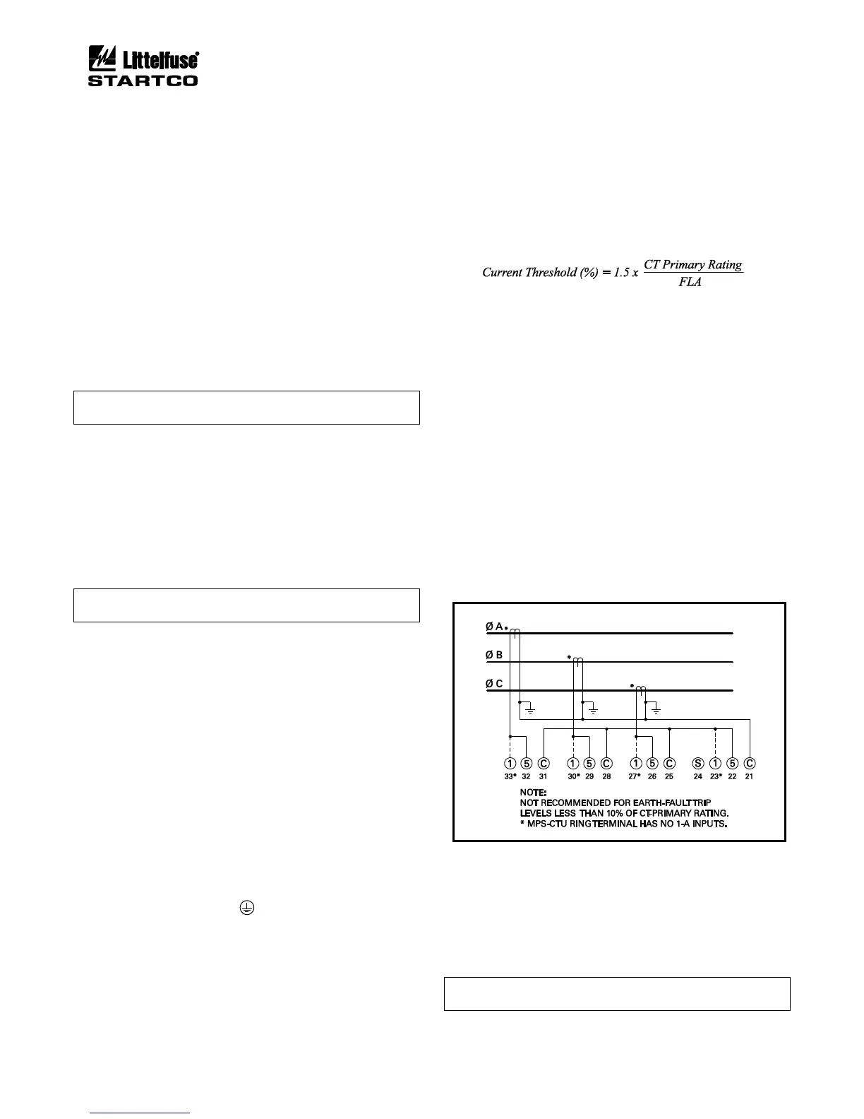
A 1-A, 5-A, or sensitive CT is used for core-balance
earth-leakage measurement. The MPS-CTU Ring
Terminal has no 1-A input. See Fig. 3.1 for the phase-CT
residual connection for earth-fault detection.
FIGURE 3.1 Residual Phase-CT Connection.
3.2.1.3 VOLTAGE INPUTS
For all input-voltage connections, the MPS-CTU
requires the phase sequence to be A-B-C with correct
polarity.
If voltage inputs are not used, connect VA, VB, and
VC to VN.
NOTE: A voltage input is required for line-frequency
metering.