Page 6-8
MPS Motor Protection System Rev. 6-F-022117
Starter Functions
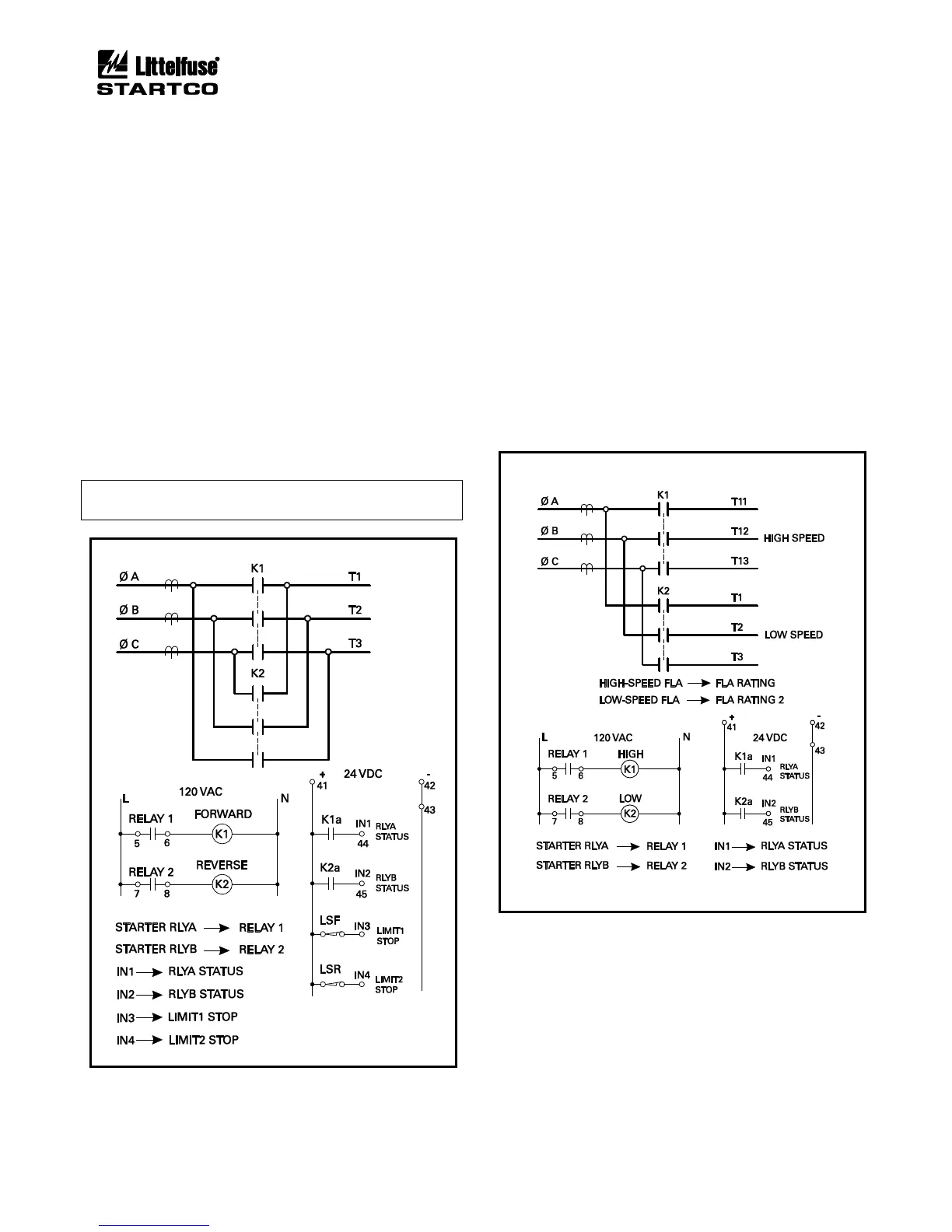
6.6 FULL-VOLTAGE REVERSING STARTER
Sequence: Fig. 6.4
Connection: Fig. 6.12
Current Transfer: Not available
The full-voltage reversing starter uses START1 to
activate Starter RLYA for forward control and START2 to
activate Starter RLYB for reverse control. RLYA Status is
the status corresponding to Starter RLYA and RLYB Status
is the status corresponding to Starter RLYB.
For OPI and 3-wire start/stop control, a direction change
requires a STOP command prior to a START1 or START2
command. For 2-wire control a STOP command is not
required.
Fig. 6.12 shows the use of forward and reverse limit
switches. When Start1 is issued, K1 is energized. If a
STOP is issued or LSF opens, K1 is de-energized. Provided
LSR is closed, Start2 will energize K2 to allow operation in
the reverse direction.
NOTE: Phase CT’s should be located upstream of the
contactors.
FIGURE 6.12 Full-Voltage-Reversing-Starter
Connection.
6.7 TWO-SPEED STARTER
Sequence: Fig. 6.4
Connection: Fig. 6.13, 6.14, and 6.15
Current Transfer: Not available
The two-speed starter uses START1 to activate Starter
RLYA for high-speed control and START2 to activate
Starter RLYB for low-speed control. RLYA Status is the
status corresponding to Starter RLYA and RLYB Status is
the status corresponding to Starter RLYB. A speed
change requires a STOP command prior to a START1 or
START2 command. This starter can be used on motors
with two separate windings (Fig. 6.13) or on motors with
reconnectable windings (Figs. 6.14 and 6.15).
This starter requires two FLA settings. Use FLA
Rating for the high-speed connection and FLA Rating 2
for the low-speed connection.
FIGURE 6.13 Two-Speed Two-Winding-Starter
Connection.