Page 6-3
MPS Motor Protection System Rev. 6-F-022117
Starter Functions
TABLE 6.2 STARTER SUMMARY
START-
CONNECTION
TIMER
NUMBER
(1)
RELAYS AND CONTACTOR STATUS
(3)
Full-Voltage Non-Reversing
Reactor or Resistor Closed-
Transition
(4)
Soft-Start-with-Bypass
(4)
Reactor or Resistor Open-
Transition
(4)
Wye-Delta Open-Transition
(4)
Autotransformer Closed-
Transition
(4)
Wye-Delta Closed-Transition
(4)
(1)
TIMERS
1: Stage 1 Delay
2: Stage 2 Delay
3: Stage 3 Delay
4: Start Time
(4)
Current transfer capability when enabled
(2)
FLA SETPOINTS
FLA: Full-Load Current
FLA2: Full-Load Current 2
(3)
RELAYS AND CONTACTOR STATUS
Starter RLYA, Starter RLYB, Starter RLYC, and
Starter RLYD are not automatically assigned. The
user must assign these functions to individual relays.
Status is assignable to any digital input.
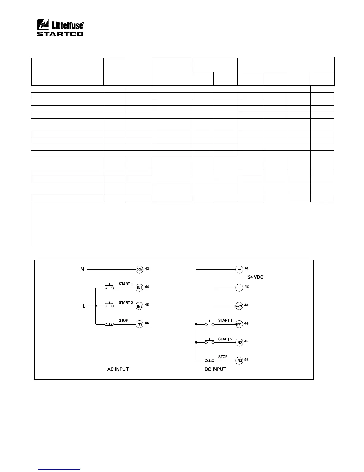
FIGURE 6.1 Typical 3-Wire Control.