Page 4-2
MPS Motor Protection System Rev. 6-F-022117
Operation and Setup
4.2.4 EARTH-FAULT-CT INPUT
OPI Menu: Setup | System Ratings | EF-CT Primary
The setting range for the earth-fault-CT-primary rating
is 1 to 5,000 A. The CT-primary rating is 5 A for
sensitive CT’s—EFCT-1 and EFCT-2.
4.2.5 VOLTAGE INPUTS
OPI Menu: Setup | System Ratings
Select the voltage-connection type (1 PT line-line, 2 PT
line-line, 3 PT line-neutral/direct) to enable voltage-
measuring functions. System Voltage is the system line-
to-line voltage. The system voltage range is 120 V to
25 kV. For the 1-PT and 2-PT connections, Input Voltage
is the PT-secondary voltage when system voltage is
applied. For the 3-PT connection, the Input Voltage is the
PT-secondary line-to-line voltage. For the direct
connection, set Input Voltage the same as the System
Voltage setting. In all cases, line-to-line voltages are
displayed.
Voltage unbalance will indicate “−” if the voltage
sequence is B-A-C. If B-A-C sequence is indicated,
correct the PT connections so that power measurements
will be valid.
NOTE: The 1-PT connection does not allow detection of
voltage unbalance.
NOTE: B-A-C sequence will cause a trip if voltage
phase-reverse protection is enabled.
4.2.6 MOTOR DATA
OPI Menu: Setup | System Ratings
OPI Menu: Setup | Protection ⏐ Overload
Motor data must be entered for the FLA Rating,
Frequency, and Service Factor. If a tachometer is used,
the Sync Speed is required. If the starter selected requires
two FLA ratings, FLA Rating 2 must be entered.
The Frequency setting determines the sampling rate
used by the MPS for current and voltage measurements.
If Sync to ASD is selected as the analog-input type, the
Frequency setting is not used and the analog output from
an adjustable-speed drive determines the sampling rate
used by current- and voltage-measuring algorithms. See
Section 5.29.2.
Locked-rotor current, cold locked-rotor time, and hot
locked-rotor time must be entered in the Protection |
Overload menu to provide customized overload
protection. See Section 5.2.
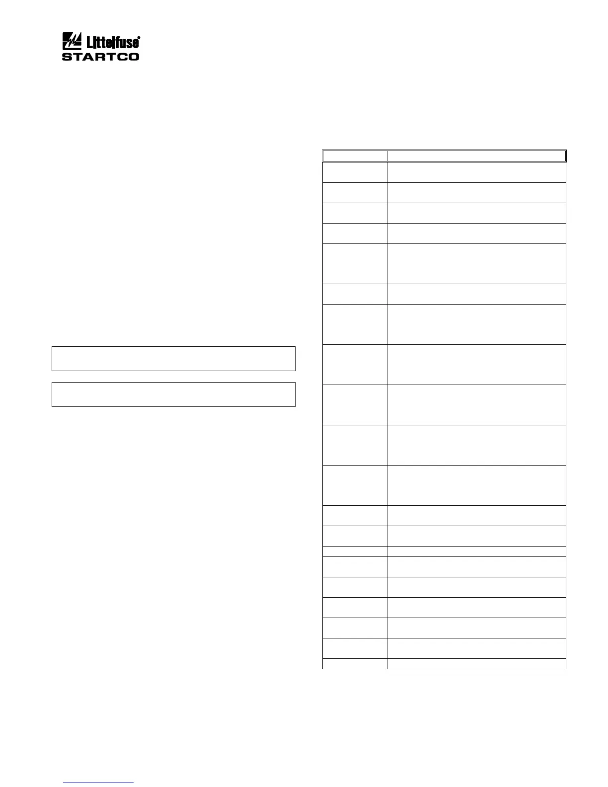
4.2.7 OUTPUT RELAY ASSIGNMENT
OPI Menu: Setup | Relay Outputs | Relay x
Each of the five output relays can be assigned to one of
the functions listed in Table 4.1. More than one relay can
be assigned the same function. Note that Relay 5 is a
solid-state relay with a low current rating and should only
be used for interlocks or annunciation.
Relay assignments Starter RLYA, Starter RLYB, Starter
RLYC, and Starter RLYD operate in conjunction with
MPS starting functions to control the motor-starter
contactor(s). See Section 6. Contactor status can be
monitored using auxiliary contacts and the digital inputs.
See Section 4.2.8 and Figs. 6.9 to 6.23.
TABLE 4.1 OUTPUT-RELAY FUNCTIONS