Page 4-4
MPS Motor Protection System Rev. 6-F-022117
Operation and Setup
Limit1 Stop and Limit2 Stop are limit-switch inputs
typically used with reversing starters. Limit1 Stop is a
stop input associated with Start1 and Limit2 Stop is a stop
input associated with Start2.
The Reduced OC selection operates in conjunction with
the reduced overcurrent set point which must be enabled.
See Section 5.5.
When Reduced OC is selected and no digital input
voltage is applied, the reduced overcurrent set point is
operational. When digital input voltage is applied, the
reduced overcurrent set point is not operational.
The following rules apply when multiple inputs are
assigned the same function:
• Start1, Start2, Local Start1, and Local Start2:
Momentary voltage on any input will initiate a start.
(MPS must be in LOCAL for Local Start1 and Local
Start2 operation.)
• Stop: Voltage must be present on all inputs to allow
an MPS-controlled start.
• Interlock: Voltage must be present on all inputs to
allow an MPS-controlled start and to energize an
interlock output relay. Digital inputs programmed as
Interlock are bypassed in LOCAL. Interlocks must
remain valid while the motor is running.
• RLYA, RLYB, RLYC, and RLYD Status: Voltage
applied to any input programmed for a contactor
status results in contactor-closed status.
• Reset: Voltage applied to any input will reset trips.
• 2-Wire Start1 and 2-Wire Start2: Voltage on any
input will initiate a start. All inputs must be open for
a stop.
• FLA2 Select: Voltage on one or more inputs assigned
to FLA2 Select will select FLA2.
4.2.9 TACHOMETER INPUT (HSI)
OPI Menu: Setup | System Ratings | Sync Speed
OPI Menu: Setup | Digital Inputs | Tachometer
This input is provided for connection to a 24-Vdc
proximity sensor for speed measurement. Set the number
of pulses per revolution and enable the High-Speed Input
in the Tachometer menu. Pulse-frequency range is 10 Hz
to 10 kHz. These two settings are required for RPM
readings.
If Failure to Accelerate protection is used, set the
motor’s synchronous speed in the Sync Speed menu. To
fully utilize a speed-setting range from 10 to 100%, a full-
speed frequency of at least 100 Hz is required.
The MPS averages 16 pulse periods to determine
speed.
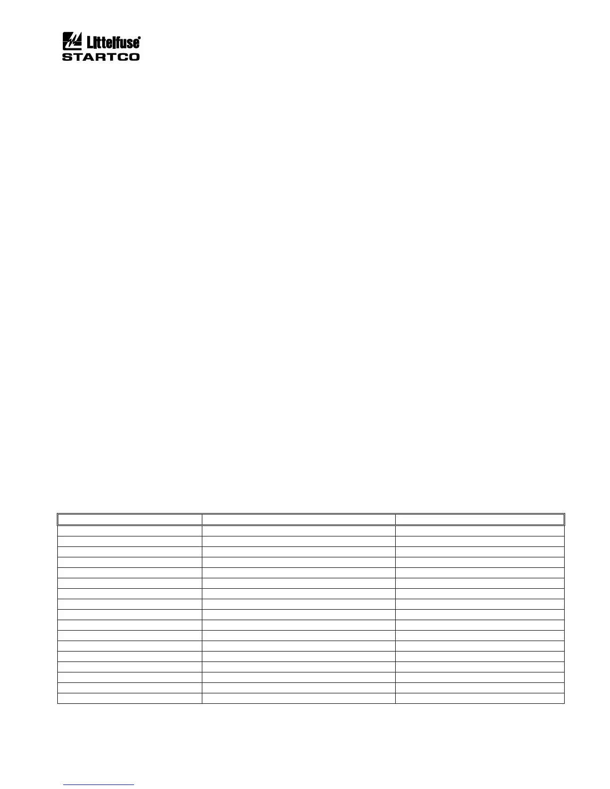
4.2.10 ANALOG OUTPUT
OPI Menu: Setup | Analog Output | Output Parameter
A 25-mA programmable current output is provided on
the CTU. Analog-output parameters are shown in
Table 4.3.
Factory calibration is 4-20 mA. If calibration is
required, use the Analog Output menus.
Zero Calibration:
• Select Zero in the Output Parameter menu.
• Measure the output current and adjust the Zero
Calibrate setting for the desired output. The
calibration number for 4 mA will be in the range of
100 to 110.
Full-Scale Calibration:
• Select Full Scale in the Output Parameter menu.
• Measure the output current and adjust the
FS Calibrate setting for the desired output. The
calibration number for 20 mA will be in the range of
540 to 550.
Calibration numbers are not changed when factory
defaults are loaded.
TABLE 4.3 ANALOG-OUTPUT PARAMETERS