Page 3-3
MPS Motor Protection System Rev. 6-F-022117
System Wiring
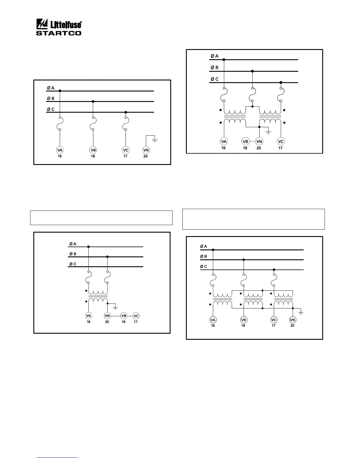
3.2.1.3.1 DIRECT CONNECTION
PT's are not required for system voltages up to 600 Vac
line-to-line. Connect the voltage inputs as shown in
Figs. 3.2 and 3.3.
FIGURE 3.3 Direct Connection.
3.2.1.3.2 1-PT CONNECTION
The 1-PT connection is shown in Fig. 3.4. Connect the
PT between phase A and phase B. The PT-secondary
voltage must be less than 350 Vac.
NOTE: The 1-PT connection does not allow detection of
voltage unbalance.
FIGURE 3.4 1-PT Connection.
3.2.1.3.3 2-PT CONNECTION
The 2-PT connection is shown in Fig. 3.5. The PT-
secondary voltages must be less than 350 Vac. Connect
the PT secondaries in open delta.
FIGURE 3.5 2-PT Connection.
3.2.1.3.4 3-PT CONNECTION
The 3-PT connection is shown in Fig. 3.6. The PT-
secondary voltages must be less than 350 Vac. Since the
MPS-CTU measures line-to-line voltage, there is no
advantage in using a 3-PT connection over a 2-PT
connection.
NOTE: This connection relies on PT primary-
magnetization current for voltage balance. Do not
connect any other secondary loads.
FIGURE 3.6 3-PT Connection.
3.2.1.4 DIGITAL INPUTS
Digital inputs 1 to 8 (terminals 44 to 51) are referenced
to COM (terminal 43). These inputs are isolated from all
other terminals and operate over a 12 to 120 Vac/Vdc
range. Inputs 1 to 7 have programmable functions. See
Table 4.2. Input 8 is a high-speed input (HSI) for a
tachometer sensor.