Page 4-8
MPS Motor Protection System Rev. 6-F-022117
Operation and Setup
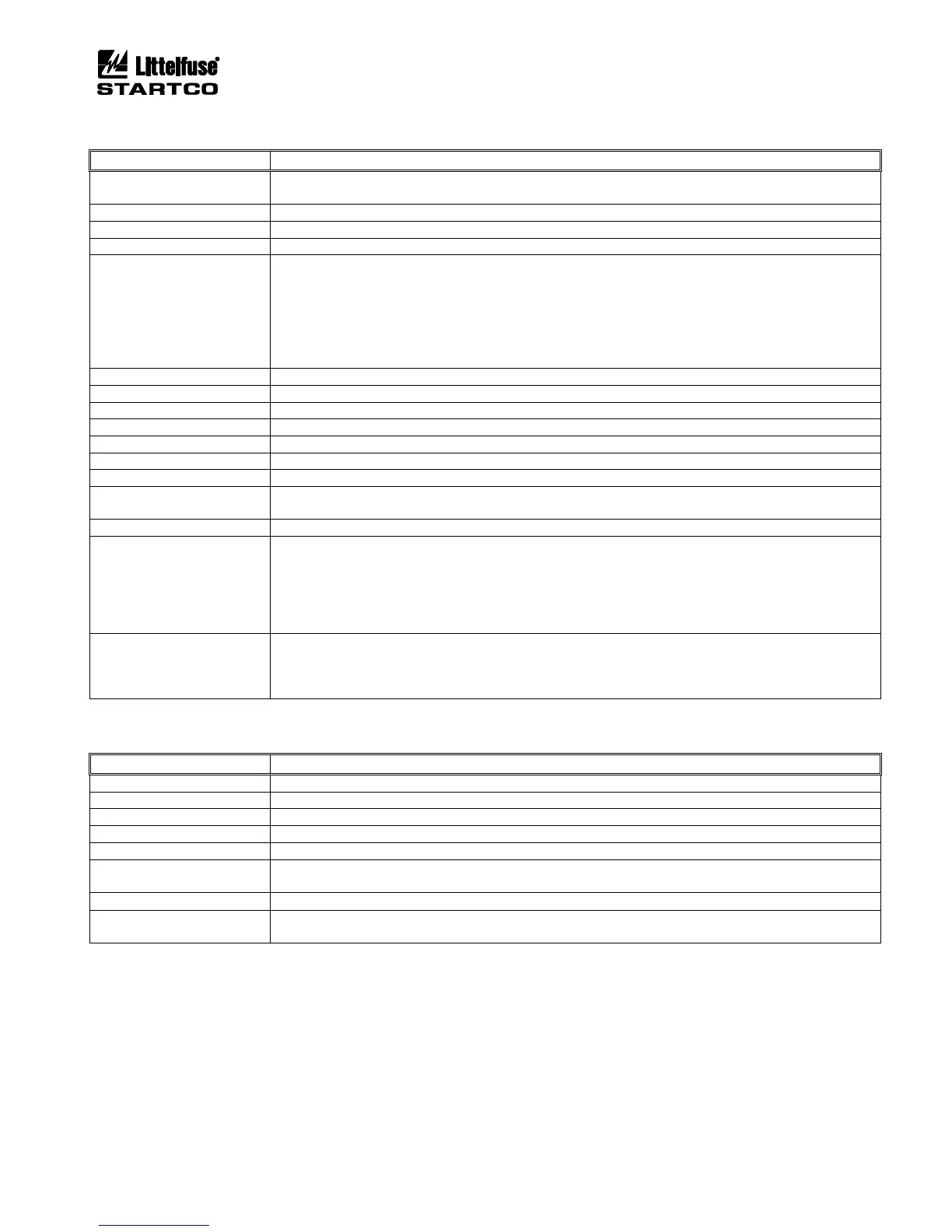
TABLE 4.4 METERING DISPLAY
Displays values as per the Meter Summary menu.
IDR, IVP, or IVPA.
I
a
, I
b
, I
c
in A and per unit of I
p
.
I
1
, I
2
, in per unit of I
p
, I
2
/I
1
in per unit.
I
g
in A and per unit of I
e
.
Used I
2
t in percent.
Trend I
2
t in percent.
Displays reset time when tripped on I
2
t.
Displays time to trip if in overload.
Displays time to I
2
t Inhibit removal.
Displays time to Starts-Per-Hour Inhibit removal.
Displays number of available starts.
V
ab
, V
bc
, V
ca
in kV and per unit of V
p
.
V
1
, V
2
, in per unit of V
p
, V
2
/V
1
in per unit.
I
1
, I
2
, in per unit of FLA, I
2
/I
1
in per unit.
DIF
a
, DIF
b
, DIF
c
in A and per unit of I
d
.
P in kW, Q in kVA, S in kVAR, PF.
V
ab
voltage in per unit of V
p
and frequency in Hz.
Summary shows maximum and minimum temperatures for stator, bearing, and load RTD’s in degrees C.
Module and input numbers, name, function, temperature in degrees C for each enabled RTD.
Analog input in mA, digital inputs and relay outputs in binary.
Date and Time, Motor Mode (Stopped, Start, Run)
Displays starter state when starter is enabled.
Displays active FLA when in protection-only mode.
Displays RPM if tachometer input is enabled.
Displays Reduced Overcurrent mode (ROC: ON, ROC: OFF)
Displays ETR mode.
Displays DF1 state as online or timed out.
Displays Modbus state as online or timed out.
Displays Anybus module error and status.
Displays DeviceNet errors and status.
(1)
All but Summary, RTD, and System State metering displays show System Name.
TABLE 4.5 STATUS MESSAGES
The interlock assigned to digital input x is open, preventing a start.
The stop switch assigned to digital input x is open, preventing a start.
The Limit1 switch assigned to digital input x is open, preventing a Start1.
The Limit2 switch assigned to digital input x is open, preventing a Start2.
The Used I
2
t has exceeded the I
2
t Inhibit level. A start is prevented if I
2
t Start Inhibit is enabled.
The number of starts per hour has been exceeded. A start is prevented if a starts-per hour trip or alarm is
enabled.
Indicates that the MPS is in ETR mode. Does not prevent a start.
When a stop is issued and the backspin timer is enabled, a start is prevented until the backspin timer
times out. This message is displayed when the backspin timer is on.