Page 3-5
MPS Motor Protection System Rev. 6-F-022117
System Wiring
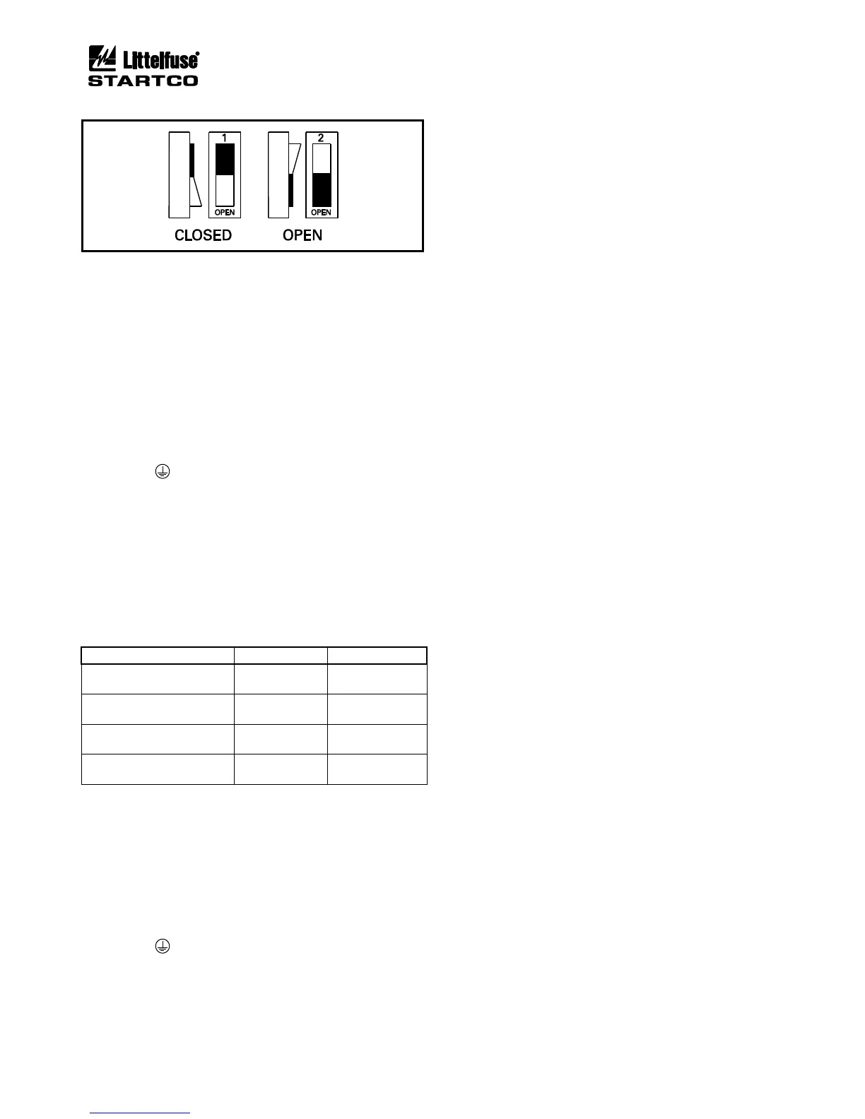
FIGURE 3.8 Address Selection Switch Detail.
3.2.3 MPS-RTD CONNECTIONS AND ADDRESS SELECTION
MPS-RTD terminal blocks accept 24 to 12 AWG
(0.2 to 2.5 mm
2
) conductors.
Connect the MPS-RTD to the MPS-CTU using the
four-conductor shielded cable (Belden 3124A or
equivalent) as shown in Fig. 3.9. The MPS-CTU 24-Vdc
supply can power up to three MPS-RTD modules.
Connect RTD’s to the MPS-RTD as shown in Fig 3.9.
When the RTD module is installed in a motor junction
box, RTD-lead shielding is not required.
Connect the surge-protection (SPG) terminal 20 to
terminal 19 ( ), and earth terminal 19.
The MPS-RTD has two switches to select its network
address. See Figs. 3.8 and 3.10. Up to three MPS-RTD
modules can be connected to the I/O MODULE bus, and
each RTD-module address must be unique. If one module
is used, address 1 must be used. If two RTD modules are
used, addresses 1 and 2 must be used. If three RTD
modules are used, addresses 1, 2, and 3 must be used.
Table 3.2 shows the addressing selection format.
TABLE 3.2 MPS-RTD ADDRESS SELECTION
3.2.4 MPS-DIF CONNECTIONS
The MPS-DIF CT-input terminal blocks accept 22 to
10 AWG (0.3 to 4.0 mm
2
) conductors. The remaining
MPS-DIF clamping blocks accept 24 to 12 AWG (0.2 to
2.5 mm
2
) conductors.
Connect the MPS-DIF to the MPS-CTU using four-
conductor shielded cable (Belden 3124A or equivalent) as
shown in Fig. 3.9.
Connect the surge-protection (SPG) terminal 15 to
terminal 14 ( ), and earth terminal 14.
3.2.4.1 CORE BALANCE
The core-balance connection is shown in Fig. 3.11. To
minimize power-cable and CT-lead length, both the
differential CT’s and the MPS-DIF can be located near
the motor. The primary rating of the differential CT does
not have to match the phase-CT primary rating and is
usually selected with a lower ratio resulting in more
sensitive differential protection. The core-balance
method avoids CT-matching issues and is the preferred
connection.
3.2.4.2 MPS SUMMATION
The MPS summation connection uses three phase CT’s
and three differential CT’s as shown in Fig. 3.12. Both
CT ratio and CT-saturation characteristics must be
matched to avoid differential currents under motor
starting and running conditions. The MPS-DIF module
should be located near the MPS-CTU to minimize CT
wire length. It is preferred to use three dedicated phase
CT’s and three core-balance differential CT’s as
described in Section 3.2.4.1.
For the delta connection, the MPS FLA Rating is set
equal to the motor’s full-load current multiplied by √3.
Power, power factor and energy measurements are not
correct for the delta connection.
3.2.4.3 DIF SUMMATION
The DIF summation connection uses six differential
CT’s as shown in Fig. 3.13. Both CT-ratio and CT-
saturation characteristics must be matched to avoid
differential currents under motor starting and running
conditions. It is preferred to use three core-balance CT’s
as described in Section 3.2.4.1. This six CT connection
allows the CT’s and MPS-DIF to be placed near the motor
to minimize power-cable and CT-lead length.
3.2.5 DIELECTRIC-STRENGTH TESTING
Dielectric-strength testing should be performed only on
CT inputs, PT inputs, output relays, and digital inputs.
Unplug all other I/O and remove the SPG connection
(terminal 4 to terminal 4A) on the MPS-CTU during
dielectric-strength testing.