Page 5-10
MPS Motor Protection System Rev. 6-F-022117
Protective Functions
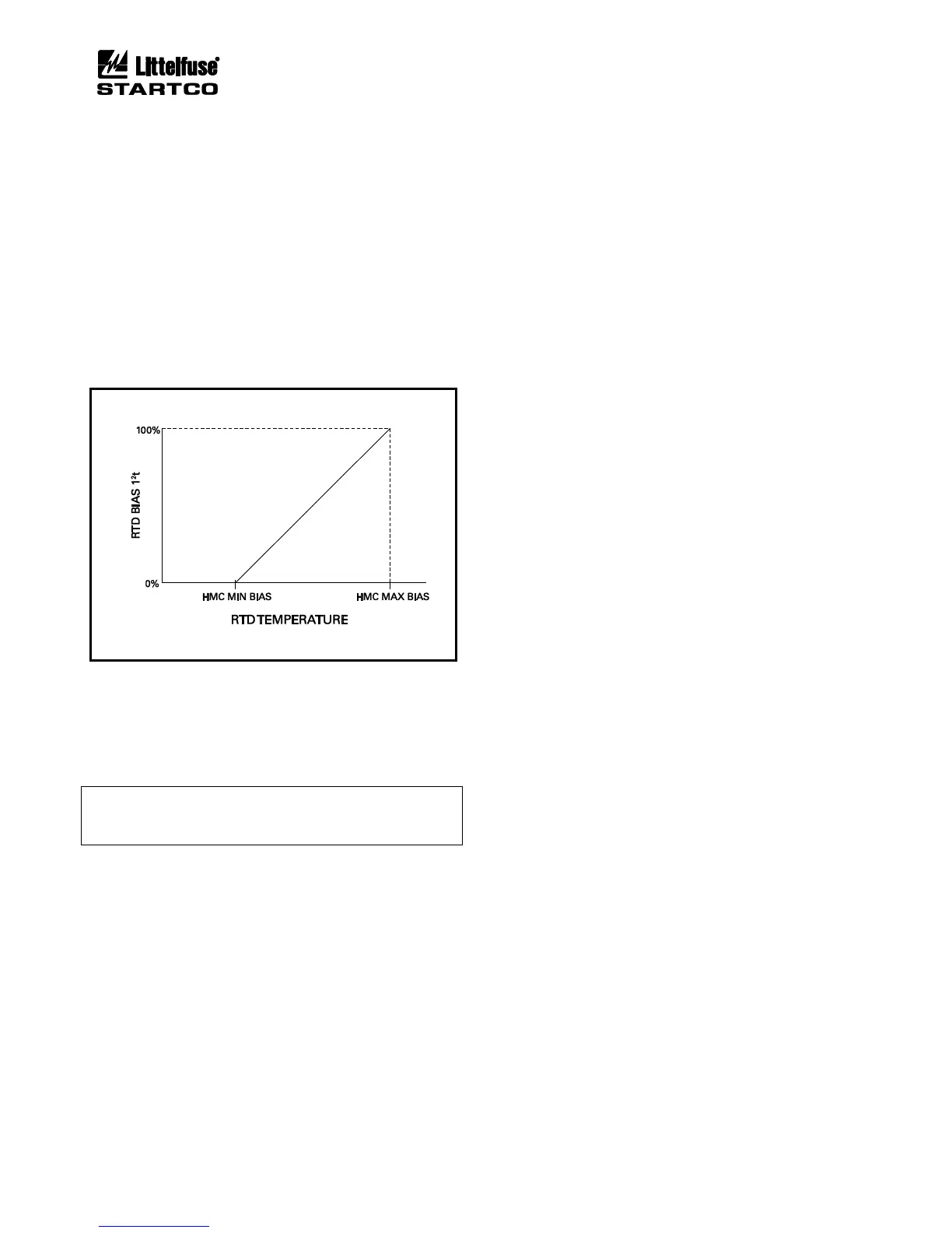
5.28 HOT-MOTOR COMPENSATION
OPI Menu: Setup | Protection | RTD Temperature
If hot-motor compensation (HMC) is enabled, the
maximum stator-RTD temperature is used to bias the
thermal model by increasing Used I
2
t when the RTD
temperature is greater than the thermal-model
temperature.
Two set points are used to define the compensation.
See Fig. 5.3. HMC Minimum Bias is the stator
temperature where compensation begins at 0% I
2
t. HMC
Maximum Bias is the stator temperature where
compensation ends at 100% I
2
t.
Although the bias calculation is based on 0% and 100%
I
2
t values, the Used I
2
t adjustment is limited to 90% I
2
t.
An actual overload condition is required to cause a trip at
100% I
2
t.
FIGURE 5.3 Used I
2
t Bias Curve.
HMC Minimum Bias ............ 40.00 to 200.00°C (104°F to
392°F)
HMC Maximum Bias ........... 40.00 to 200.00°C (104°F to
392°F)
Protection .............................. Enable/Disable
NOTE: Hot-motor compensation will not be active unless
the HMC High set point is at least 10°C above the HMC
Low set point.
5.29 ANALOG INPUT
OPI Menu: Setup | Analog Input | 4–20 Input Type
The analog input function is selectable as Metering
Only, Protection, Sync to ASD, or Motor Speed.
5.29.1 PROTECTION
OPI Menu: Setup | 4-20 Analog In | Protection
The protection input has high-level and low-level trip
and alarm set points. A high-level trip or alarm occurs
when the 4-20-mA input exceeds the high-level trip or
alarm set point, and a low-level trip or alarm occurs when
the 4-20-mA input is lower than the low-level trip or
alarm set point.
Trip action is fixed at Trip1 and alarm action is fixed at
Alarm1.
High Level Trip .................... 0.10 to 20.00 mA
Low Level Trip ..................... 0.10 to 20.00 mA
Trip Delay ............................. 0.01 to 100.00 s
High Level Alarm ................. 0.10 to 20.00 mA
Low Level Alarm ................. 0.10 to 20.00 mA
Alarm Delay ......................... 0.01 to 100.00 s
5.29.2 SYNCHRONIZE TO ASD
OPI Menu: Setup | 4-20 Analog In | Sync to ASD
When Sync to ASD is selected, the MPS uses the
4-20-mA input to set the internal sampling rate for current
and voltage inputs so that protection and metering
functions use accurate RMS and DFT values from 10.00
to 70.00 Hz.
4-mA Frequency (lower) ...... 0.00 to 70.00 Hz
20-mA Frequency (upper) .... 0.00 to 70.00 Hz
Frequency Range .................. 10.00 to 70.00 Hz
5.29.3 MOTOR SPEED
OPI Menu: Setup | 4-20 Analog In | Motor Speed
When the analog-input type is selected as Motor Speed,
the 4-20-mA analog input is used as the speed input. This
selection overrides the selections for the high-speed
tachometer input and failure-to-accelerate protection uses
the analog input as the source of speed information.
4-mA Speed .......................... 0.00 to 100% Sync Speed
20-mA Speed ........................ 0.00 to 100% Sync Speed
5.29.4 METERING ONLY
When the analog-input type is selected as Metering
Only, an analog input does not affect MPS operation, but
its value can be observed in the Metering menu and with a
communications network.