Page 4-1
MPS Motor Protection System Rev. 6-F-022117
Operation and Setup
4. OPERATION AND SETUP
4.1 GENERAL
The MPS-CTU can operate independently. It can also
operate in conjunction with network communications, the
MPS-OPI, MPS-RTD and the MPS-DIF. All settings are
stored in the MPS-CTU and can be accessed using the
OPI or the network communications interface. Use
SE-Comm-RIS software and an SE-485PP or SE-485-DIN
serial converter to program with a personal computer.
In the following sections, menu items and setup
parameters are listed in italics and are shown in the format
displayed on the OPI. The OPI cannot display subscripts
and superscripts.
Menu selection is in the following format:
Menu 1 | Sub Menu 1 | Sub Menu 2 | Sub Menu 3 |……
Example: For the menu item shown in Fig. 4.1, the
notation is Setup | System Ratings | CT Primary
FIGURE 4.1 Menu Example.
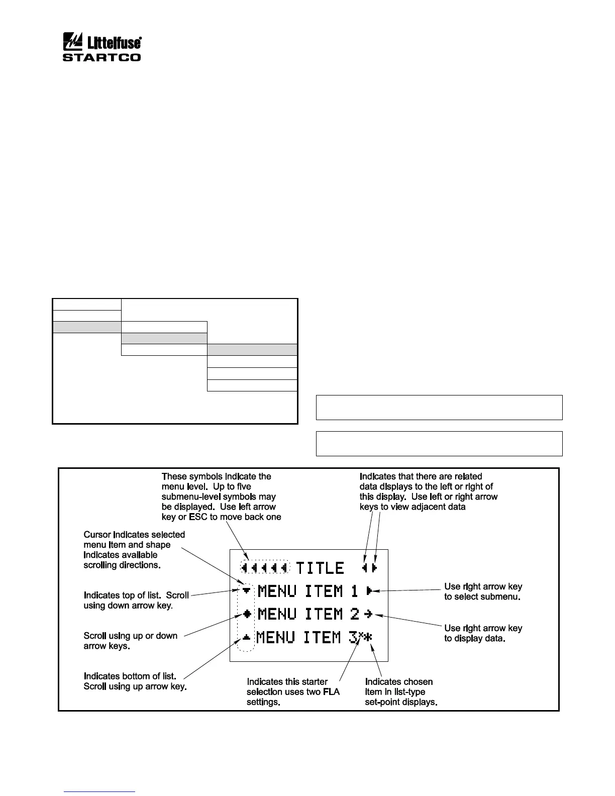
Fig. 4.2 shows the symbols that assist in navigating the
menu system and how these symbols relate to the arrow
keys on the MPS-OPI. See the menu map in Appendix A.
4.2 MPS-CTU
4.2.1 LED INDICATION
The four LED’s on the MPS-CTU indicate POWER
(green), TRIP (red), ALARM (yellow), and ERROR
(red). The POWER LED is ON when supply voltage is
present. The TRIP and ALARM LED’s indicate a trip or
alarm condition. The ERROR LED is ON during
firmware updates or when there is an MPS-CTU failure.
4.2.2 RESET SWITCH
The reset switch is used to simultaneously reset all
trips. Trips cannot be held off by a maintained closure.
4.2.3 PHASE-CT INPUTS
OPI Menu: Setup | System Ratings | CT Primary
The setting range for the CT-primary rating is 1 to
5,000 A. To maintain specified accuracy, phase CT’s
should be selected with a primary rating between 100 and
300% of motor full-load current.
Current unbalance will indicate “−” if the current
sequence is B-A-C. If B-A-C sequence is indicated,
correct the CT connections so that power measurements
will be valid.
NOTE: B-A-C sequence will cause a trip if current phase-
reverse protection is enabled.
NOTE: Phase-unbalance and phase-loss testing requires
three-phase inputs to the MPS.
FIGURE 4.2 Menu Symbols.