Page 3-4
MPS Motor Protection System Rev. 6-F-022117
System Wiring
3.2.1.4.1 DC OPERATION
Supply voltage for dc-input operation can be obtained
from the 24-Vdc source (terminals 41 and 42), or it can be
obtained from an external 12- to 120-Vdc supply.
The internal source is current limited at 100 mA and is
referenced to the analog output (terminal 40) and the I/O
Supply (terminal 56). Connect the “−” terminal of the dc
source to COM and connect field inputs between “+” and
the digital-input terminals.
3.2.1.4.2 AC OPERATION
Inputs operate over a 12- to 120-Vac range. Connect
the ac neutral to COM and connect field inputs between
line and the digital inputs.
3.2.1.4.3 COMBINED AC AND DC OPERATION
If both ac and dc inputs are used, connect both the ac-
supply common and dc-supply “−” to COM.
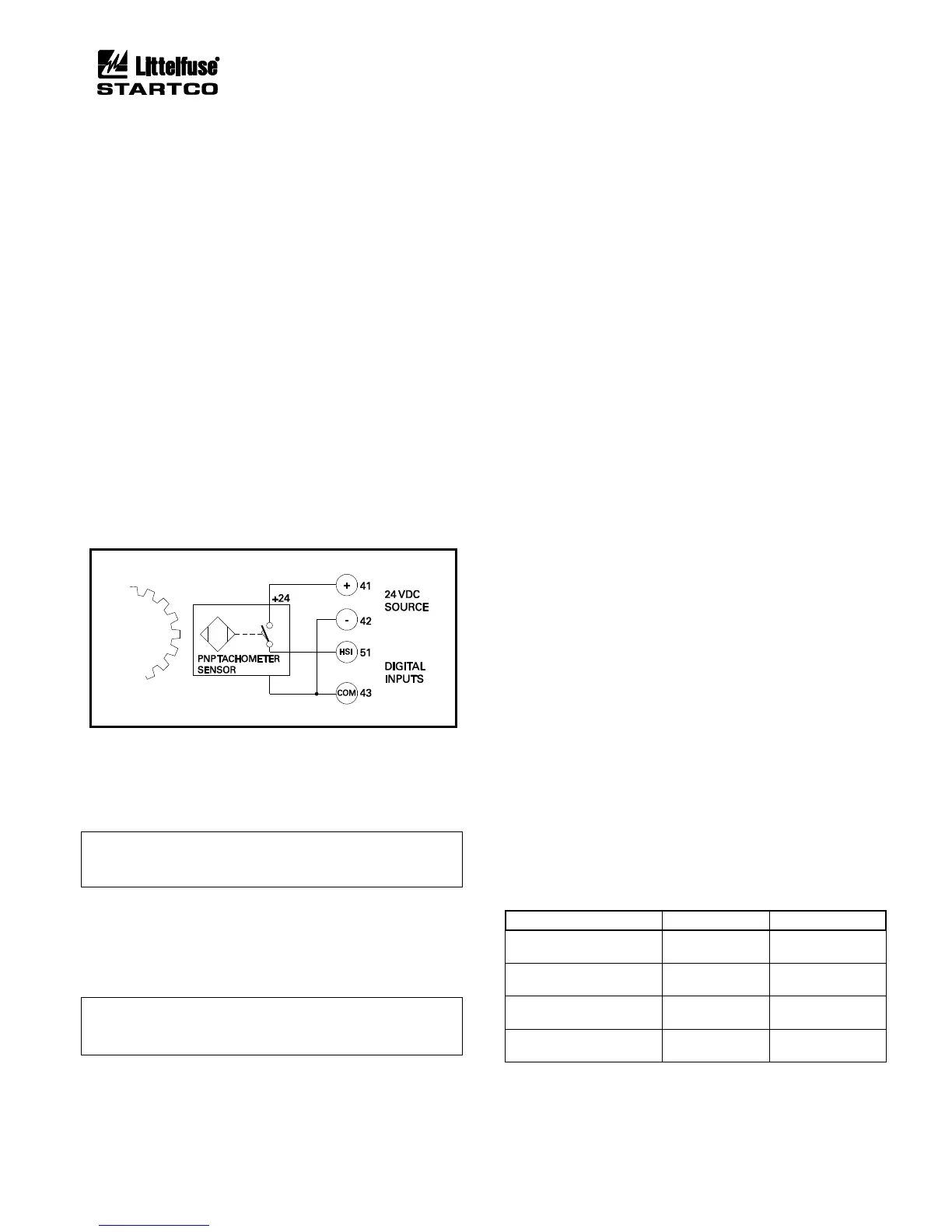
3.2.1.4.4 TACHOMETER INPUT (HSI)
A tachometer sensor can be used to provide motor-
speed measurement. Connect a logic-output PNP
tachometer as shown in Fig. 3.7.
FIGURE 3.7 Digital Tachometer Input (HSI).
3.2.1.5 ANALOG INPUT (AN IN)
The analog input (terminal 52 and 53) is a 4-20-mA
current input with a 100-Ω input impedance.
NOTE: The analog input is referenced to an internal
supply with 100-kΩ resistors. Maximum common-mode
voltage is ± 5 Vdc with respect to MPS-CTU terminal 4.
3.2.1.6 ANALOG OUTPUT (AN OUT)
The analog output is a self-powered current-source
output. The current source output is the “+” (terminal 39)
and the common is “−” (terminal 40).
NOTE: The analog output (terminal 40) is internally
referenced to the 24-Vdc source (terminal 42) and the I/O
supply (terminal 56).
3.2.1.7 PTC INPUT
Terminals 54 and 55 are provided for PTC over-
temperature protection. See Section 9 for specifications.
3.2.1.8 IRIG-B INPUT
Terminals 61 and 62 are used for an IRIG-B time-code
signal. When an IRIG-B signal is detected, the real-time
clock (RTC) synchronizes with it. The user must set the
MPS date value because the IRIG-B day-of-the-year
parameter is not supported.
If the time-code generator does not have a local-time
adjustment, the IRIG Offset set points can be used to
adjust the hour and minute values so that the MPS will
read local time.
3.2.1.9 I/O MODULE COMMUNICATION
The I/O module communications interface (terminals
56 through 60) is used to support optional modules. The
connector labeled Operator Interface on the MPS-CTU
top panel is in parallel with terminals 50 to 56. It is used
for direct MPS-OPI mounting. See Section 2.3.
I/O module communication is based on the 2-wire
multi-drop RS-485 standard. Overall line length must not
exceed 1.2 km (4,000’). For line lengths exceeding
10 m (33’), 150-Ω terminations are required at the cable
ends. See Fig. 3.9.
3.2.1.10 RS-485 NETWORK COMMUNICATIONS
Terminals 35, 36, and 37 are used for the standard
RS-485 interface. See Section 4.2.15.
3.2.2 MPS-OPI CONNECTIONS AND ADDRESS SELECTION
Connect the MPS-OPI to the MPS-CTU using shielded
cable (Belden
®
3124A or equivalent). The 24-Vdc supply
for the MPS-OPI is provided by the MPS-CTU. The
cable shield must be connected at both ends so that
MPS-OPI transient protection is operational. See Fig. 3.9.
The MPS-OPI has two switches to select its network
address. See Figs. 2.2 and 3.8. Up to three MPS-OPI
modules can be connected to the I/O MODULE bus, and
each active OPI must have a unique address. If one OPI
is used, address 1 must be used. If two OPI's are used,
addresses 1 and 2 must be used. If three OPI's are used,
addresses 1, 2, and 3 must be used.
Table 3.1 and Fig. 3.8 shows the addressing selection
format.
TABLE 3.1 MPS-OPI ADDRESS SELECTION