Page 6-7
MPS Motor Protection System Rev. 6-F-022117
Starter Functions
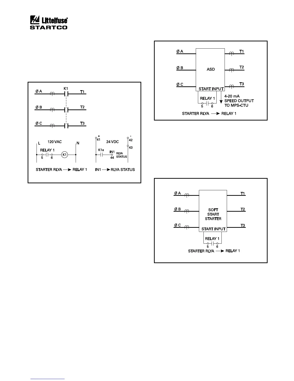
6.3 FULL-VOLTAGE NON-REVERSING STARTER
Sequence: Fig. 6.3
Connection: Fig. 6.9
Current Transfer: Not available
START1 or START2 is the start command and Starter
RLYA is used as the output to control the contactor.
FIGURE 6.9 Full-Voltage Non-Reversing-Starter
Connection.
6.4 ADJUSTABLE-SPEED DRIVE
Sequence: Fig. 6.3
Connection: Fig. 6.10
Current Transfer: Not available
The MPS-CTU provides the start input to an
adjustable-speed drive (ASD). START1 or START2 is
the start command and Starter RLYA is used as the output
to control the ASD.
The MPS-CTU has a 4-20 mA input that should be
used to synchronize its sampling rate to the ASD output
frequency so that all protection and metering values are
valid for an ASD output frequency from 10 to 70 Hz. In
ASD applications, voltage and current inputs must be
derived from the load side of the ASD, and undervoltage
protection must be disabled.
FIGURE 6.10 Adjustable-Speed-Drive Connection.
6.5 SOFT-START STARTER
Sequence: Fig. 6.3
Connection: Fig. 6.11
Current Transfer: Not available
The MPS-CTU provides the start input to a solid-state
starter. START1 or START2 is the start command and
Starter RLYA is used as the output to control the starter.
FIGURE 6.11 Soft-Start-Starter Connection.