- 66 - Workshop Manual LDW CHD _ cod. 1.5302.345 - 6° ed_rev. 05
150
149
148
147
8
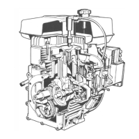
Fuel feeding/injection circuit
Components:
1 - Tank
2 - Fuel feeding pump
3-Fuellter
4 - Fuel delivery tube
5 -Injectorpumpsoverowtube
6 - Injection pump
7 - High-pressure tube between pump and injector
8 - Injector
9 - Injector return tube
10 - Solenoid valve
Fuel feeding pump drive rod protrusion
Push rod 2 shows a protrusion A of 1.5÷1.9 mm from the
crankcase
plane. Check this value with eccentric 1 at the lowest point
(on
the bottom of the cam base of the camshaft).
Push rod length = 32.5÷32.7 mm.
Check push rod length and replace push rod if size is
inadequate.
Fuel feeding pump
Components:
1 - Feeding pump
2 - Push rod
3 - Seal ring
The fuel feeding pump is of the diaphragm type operated by a
camshaft eccentric through a push rod.
If features an external lever for manual operation.
Fuel lter
Components:
1 - Drain screw
2 - Cover
3 - Seal
4 - Fitting
5 - Cartridge
Cartridge specications
Filtering paper:.....................PF 904
Filtering area:.......................5000 cm2
Filtering degree:...................2/3 m
Max. working pressure: ....... 4 bar
See page 22 for maintenance details.
FUEL SYSTEM

 Loading...