PyroTec™ PRO Hardw are User’s Manual, V1.2 52
RT-MN024-1.2 02/21
Termination
The CAN bus termination must be adapted to the individual configuration of the instru-
ment. For this reason, most PCBs have either jumpers or switches to connect the termina-
tion resistors, where appropriate.
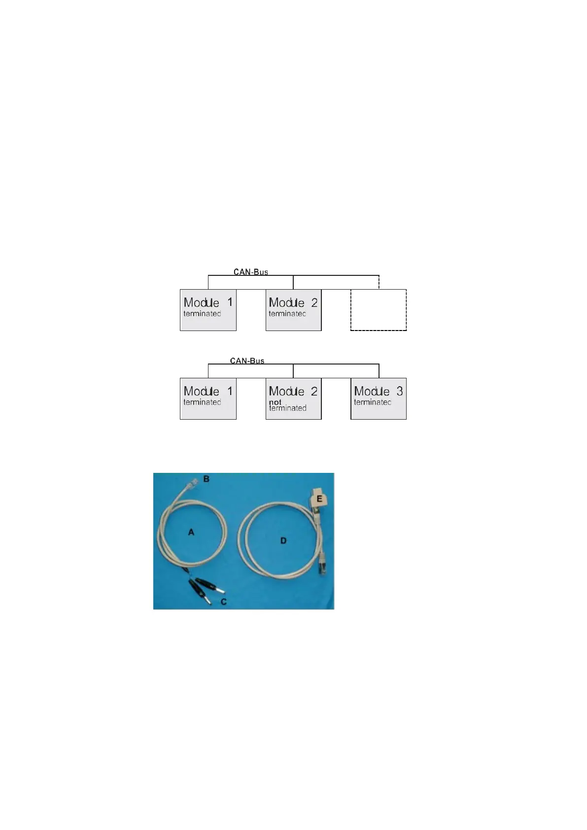
In every case two participants of a CAN bus string must be terminated.
The example below shows how the implementation of an additional module (e.g. Module
3) may affect the CAN bus termination. Which modules exactly must be terminated de-
pends on the position of the module.
To check the termination, use the special cable to measure the resistance of the CAN bus
string.
Measuring cable (A) with RJ45 connector
(B) to PCB and plugs (C) to connect a multi-
meter Adapter cable (D) with distributor (T-
piece, E), used if all RJ45 connectors on the
PDB are occupied.
In this case, unplug one option. Connect the
adapter cable between the PCB and the
measuring cable and connect the option to
the T-piece.
Check the
Termination
Check the jumper or switch settings for the CAN bus termination as follows:
• Open the left access door.
Note: Make sure that the instrument is switched off while measuring the CAN bus re-
sistance.