PyroTec™ PRO Hardw are User’s Manual, V1.2 53
RT-MN024-1.2 02/21
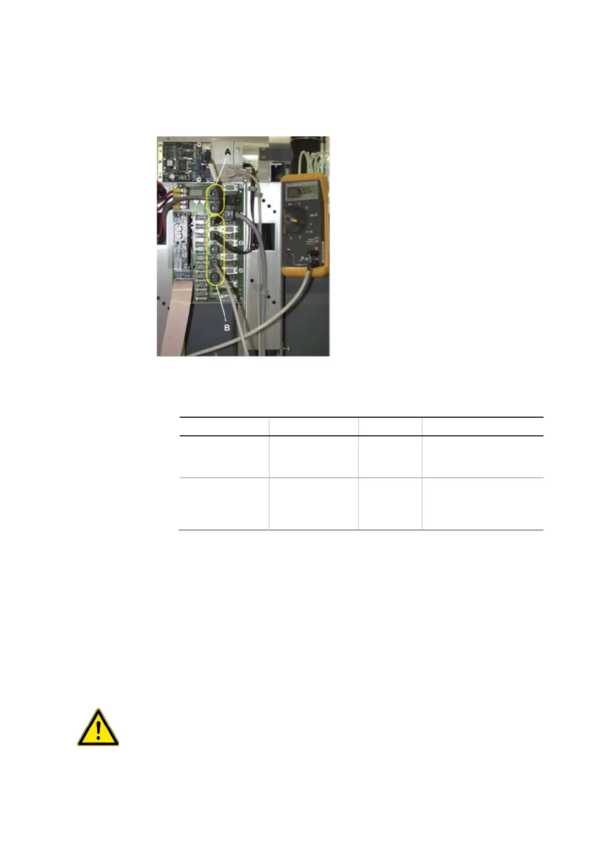
• Connect the multimeter to the RJ45
connector of the corresponding PCB (in
most cases the Optibo DCU).
• Measure the CAN bus resistance.
A – Low CAN (or Local CAN)
B – High CAN (or Option CAN)
• Set the jumpers or switches on the corresponding PCB according to the following ta-
ble:
RJ45 on Optibo DCU,
SMIO/SAFY
W
W
Correct number of jumpers
1 jumper redundant
RJ45 on Optibo DCU,
corresponding test
points on PCBs
W
W
Correct number of jumpers
1 jumper redundant
6.5 Installing Options
the Option
For information on how to install the option, refer to the Service Manual of the respective
option.
6.5.1 Modifications on Safety Panels
on the Safety
Panels
Some options for the PyroTec™ PRO require modifications on the safety panels. These
modifications must be performed by an authorized Lonza FSE (field service engineer) when
the option is installed.
If the options require modifications on the PyroTec™ PRO are installed improperly, the
safety concept may be impaired.