PyroTec™ PRO Hardw are User’s Manual, V1.2 51
RT-MN024-1.2 02/21
6.3 Installing and Connecting
Note: Unless otherwise specified a contracted field specialist will perform this proce-
dure.
6.3.1 PyroTec™ PRO Instrument
Movement
Check
To check the mechanics, manually move the axes of all modules and options slowly to
their end positions. All axes must move smoothly without any jerking.
Note: The LiHa and RoMa arms are equipped with Z-brakes. Therefore, these axes cannot
be checked when the instrument is off.
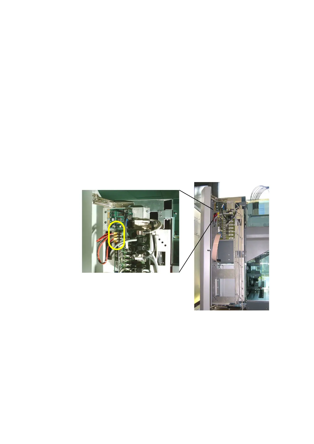
Check the screw terminals of the power supply as follows:
• Open the left access door.
• Tighten the four screw terminals on the Option DCU.
6.4 Checking the CAN Bus Resistance
Strings
To control the different modules and options of the PyroTec™ PRO there are CAN bus
strings on two different levels:
• High CAN (or Option CAN [communication with modules and optional])
• Low CAN (or Local CAN [communication within modules and options, e.g. liquid han-
dling system, Front Loading ID, etc.])
 Loading...