Chapter 7 Input/Output Specifications
7-6
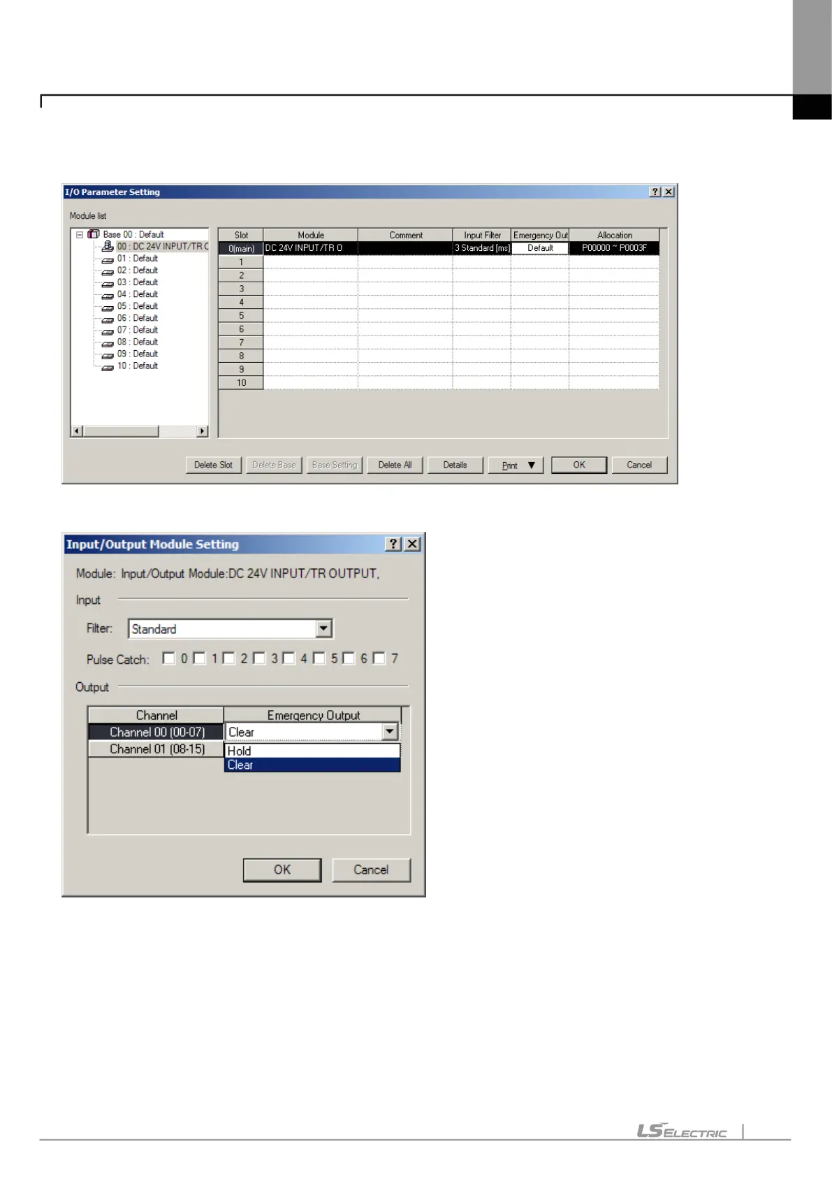
(b) Setting output status in case of error
1) Click Emergency Out in the I/O parameter setting window.
2) Click Emergency Output.
If it is selected as Clear, the output will be Off and if Hold is selected, the output will be kept.