Chapter 4. CPU Specifications
4-3
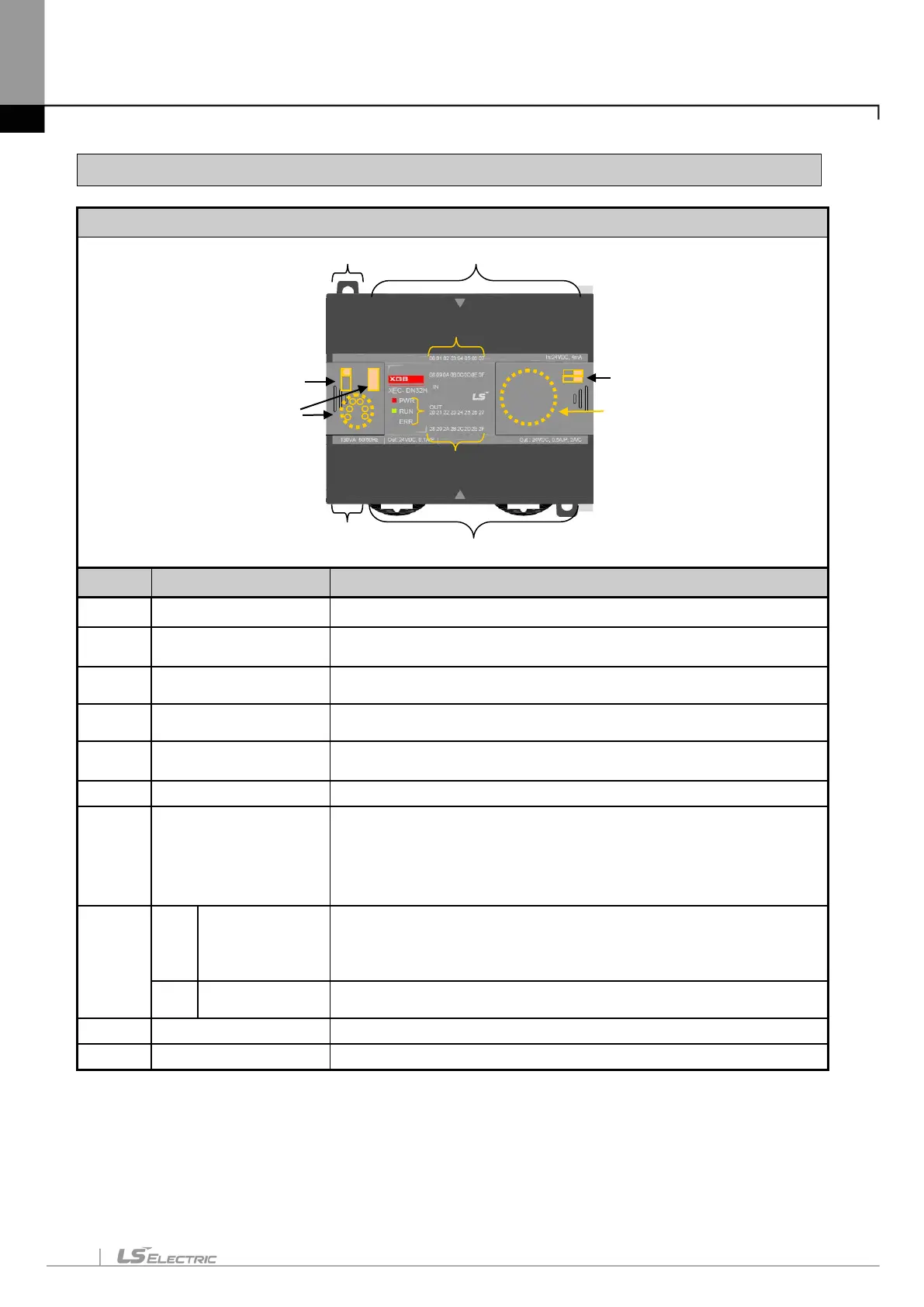
4.2 Names of Part and Function
XGB Compact type main unit (IEC language)
No. Name Description
①
Input indicator LED
▪ Input indicator LED
②
PADT connecting
connector
▪
PADT connecting USB (USB 1.1 supported) 1 channel,
RS-232C 1 channel connector
③
Input connector and
terminal block
▪ Input connector and terminal block
④
Output connector and
terminal block
▪ Output connector and terminal block
⑤
Key switch
▪
RUN / STOP Key switch
In case of STOP mode, Remote mode changeable.
⑥
Output indicator LED ▪ Output indicator LED
⑦
Status indicator LED
It indicates CPU module’s status.
▪ PWR(Red): Power status
▪ RUN(Green): RUN status
STOP mode: Off/ RUN mode : On
▪
Error(Red): In case of error, it is flickering.
⑧
8-1
/ RS-485
Connecting
Built-in RS-485 connecting connector
“+” , “-“ terminal connecting connector in RS-485 communication
▪ Built-in RS-232C connecting connector
“TxD” , “RxD“ , “GND” connecting connector in RS-232C
8-2
▪ AC100~240V power supply connector
⑨
Battery holder ▪ Battery (3V) holder
⑩
Mode switch
▪ Program mode and O/S download mode select switch
①
②
④
⑤
⑥
③
⑦
8-1
8-2
⑨
⑩