Chapter 10. Maintenance
10-1
Chapter 10 Maintenance
Be sure to perform daily and periodic maintenance and inspection in order to maintain the PLC in the best conditions.
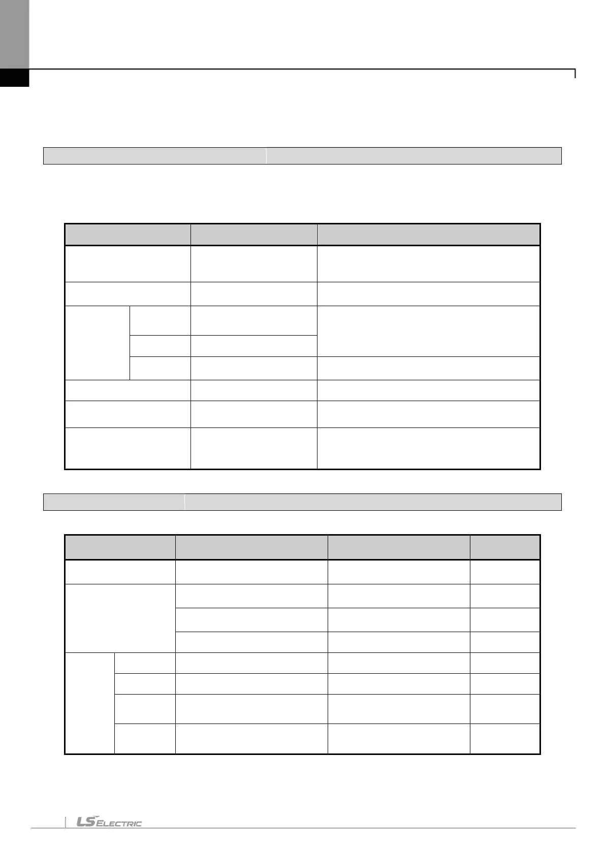
10.1 Maintenance and Inspection
The I/O module mainly consist of semiconductor devices and its service life is semi-permanent. However, periodic
inspection is requested for ambient environment may cause damage to the devices. When inspecting one or two times
per six months, check the following items.
Check Items Judgment Corrective Actions
Change rate of input voltage
Within change rate of input
voltage
(Less than −15% to +20% )
Hold it with the allowable range.
Power supply for input/output
Input/Output specification of
each module
Hold it with the allowable range of each module.
Ambient
environment
Temperature
0 ~ + 55℃
Adjust the operating temperature and humidity with the
defined range.
Humidity
5 ~ 95%RH
Vibration
No vibration
Use vibration resisting rubber or the vibration prevention
method.
Play of modules
No play allowed Securely enrage the hook.
Connecting conditions of
terminal screws
No loose allowed Retighten terminal screws.
Spare parts
Spare parts and their
Cover the shortage and improve the conditions.
10.2 Daily Inspection
The following table shows the inspection and items which are to be checked daily.
Check Items Check Points Judgment
Connection conditions of
Input/Output module
Check the connecting screws
Check module cover.
Screws should not be loose.
Connecting conditions of
terminal block or extension
cable
Check for loose mounting screws.
Screws should not be loose.
Check the distance between solderless
terminals.
Proper clearance should be provided. Correct.
Connecting of expansion cable. Connector should not be loose. Correct.
LED
indicator
PWR LED
Check that the LED is On.
On(Off indicates an error) See chapter 5.
Run LED Check that the LED is On during Run. On (flickering indicates an error) See chapter 5.
Input LED Check that the LED turns On and Off.
Off when input is off.
See chapter 5.
Output LED Check that the LED turns On and Off
Off when output is off
See chapter 5.