Chapter 9. Installation and Wiring
9-4
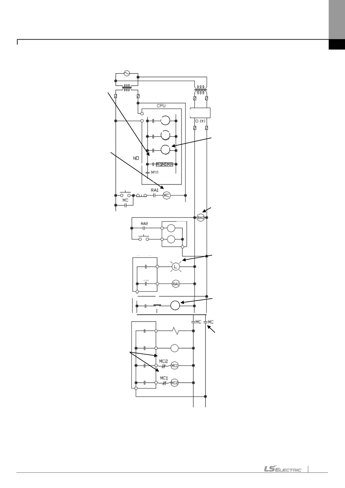
(2) System design circuit example (In case of using ERR contact point of power module)
current
Signal input
which DC input
signal is
configured.
(Lamp or buzzer)
(
stop by limit)
lead opposite operation
or breakdown such as
interlock circuit
forward, reverse
revolution by external
interlock circuit
Pm
Pm
F0045
F009C
ERR
to output device
equipped
Available to start as
RA1
In case of AC DC
(1) Run CPU after turning on power.
(2) Turn on RA2 with DC power supplied
(3) Turn on timer after DC power is stable
(4) Turn on start switch Output device runs by program through magnetic
contactor (MC) [On]
Fuse
Fuse
SW