MERLIN LEGEND Communications System Release 6.1
System Manager’s Guide
555-661-118
Issue 1
August 1998
System Components
Page 3-4Control Unit
3
Power Supply Module 3
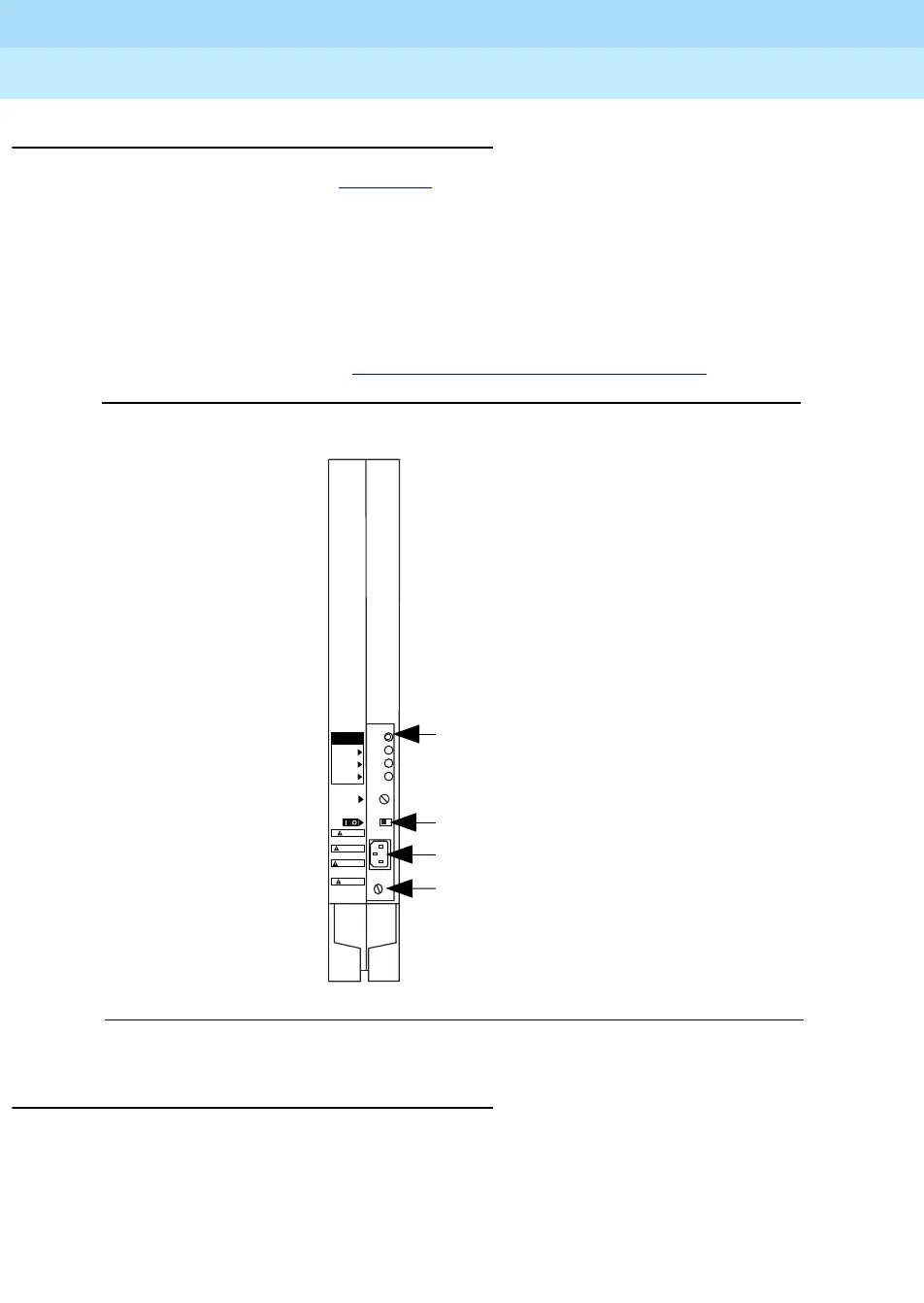
The power supply module (Figure 3–2) provides power to the carrier, to each
telephone, and to most adjuncts. (Some adjuncts, such as fax machines, come
with their own power supplies and do not rely on the system.) Each carrier
requires its own power supply module, installed in the carrier’s leftmost slot. The
current power supply module is the 391C1; it works with all releases of the
system.
In some systems, you need extra power supplies to support your system
components as described in “Power-Related Hardware” on page 3–46
.
Figure 3–2. Power Supply Module
Line/Trunk and Extension Modules 3
Line/trunk and extension modules have jacks for connecting telephone company
lines/trunks and extension wires to the control unit. The system supports 17 types
of line/trunk and extension modules. For maximum flexibility, some modules
support only lines/trunks, some only extensions, and some a combination of the
two.
Power Indicator (Green Light)
On/Off Switch
Power Connection
Grounding Screw
POWER
BATTERY BACK UP
+5V
-5V
-48V
AC INPUT
ON/OFF
TURN OFF SWITCH THEN REMOVE
POWER CORD BEFORE INSERTING OR
REMOVING UNIT.
3
2
1
TEST PORTS
CAUTION
ETEIGNEZ L'APPAREIL ET D´EBRANCHEZ
LA PRISE AVANT D'INTRODUIRE OU DE
RETIRER DES MODULES.
ATTENTION
APAGUE EL INTERRUPTOR DESPUES
REMUEVA EL CABLE ELECTRICO
INSERTANDO O REMOVIENDO LA
UNIDAD
PRECAUCION
ZUERST ABSCHALTEN, DANN DAS
STROMKABEL ENTFERNEN, EHE DAS
GERAT EINGESETZT ODER ENTFERNT
WIRD.
VORSICHT

 Loading...