OPERATION
PREPARING THE TRACTOR
1. Select proper tractor
size
.
The
min
i
mum
power required
is
:
12
ft
. -
60
hp
(4~5
kw)
14
ft
. -
75
hp
(56
kw)
16
ft.
-
90
hp
(613
kw)
Also, minimum hydraulics required
a.re
1750
psi
(12000 kPa) pressure
with
doublE~
acting.
dua
l
remote
capabi
lity
.
2.
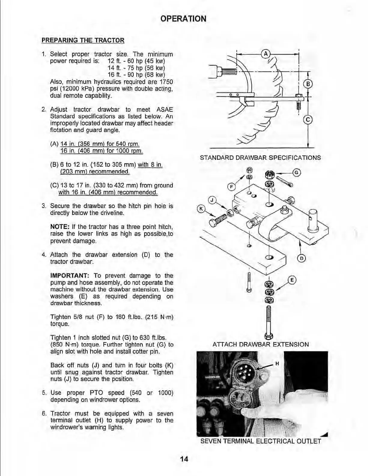
Adjust tractor drawbar to meet ASAE
Standard specifications
as
listed
below.
An
improperly located drawbar
may
affect header
flotation
and
guard
ang
l
e.
(Al
14
in
. (356
mm)
for 540
rpm
.
16 in. (406
mm)
for 1000
rpm
.
(8)
6 to 12 in. (152 to 305 mm) with 8
in
.
(203
mm)
recommended.
(e)
13
to
17
in
. (330 to 432
mm)
from ground
with
16
in. (406 mm) recommended.
3.
Secure the drawbar
so
the
hitch
pi
n hole
is
directly
be
low
the
driveline.
NOTE: If the tractor has a three point hitch,
raise the lower links
as
high
as
po.ssible,
to
prevent damage.
4.
Attach the drawbar extension
(0)
to the
tractor drawbar.
IMPORTANT: To prevent damage
to
the
pump and hose assembly, do
not
ope!rate
the
machine without the drawbar extensi:
on.
Use
washers (E)
as
required depencling
on
drawbar thickness.
Tighten
5/8 nut (F)
to
160
ft.lbs.
(215 N
'm)
torque.
Tighten 1 inch stotted nut
(G)
to
630 tUbs.
(850
N'm) torque. Further tighten nut (G)
to
align slot with hole
and
install cotter pin.
Back off nuts
(J)
and
tum
in
four bolts
(K)
until snug against tractor drawbar. Tighten
nuts
(J) to secure the position.
5. U
se
proper PTO speed (540
0;('
1000)
depending
on
windrower options.
6. Tractor must
be
equipped with
~I
seven
terminal
outlet (H) to supply power to the
wind
rower's warning lights.
14
STANDARD
DRAWBAR
SPECIFICATI
ONS
ATTACH DRAWBAR EXTENSION
~
iMfr;iAL-ELE'CTRIC.
AL
OU
TLET