UNLOADING
& ASSEMBLY
INSTALL
GAUGE
WHEEL
I TRANSPORT OPTION
30 & 36
FT.
NOTE: These instructions apply to
the
gauge
wheels with transport option. For instructions for
installing the standard gauge
wheel
package,
see
previous page.
1.
Remove chain hooks and move lifting vehicle
to rear
of
header. Attach chain to center link
anchor
on
frame tube
and
raise rear of
header.
2.
Identify right and left
wheel
supports: Left
wheel support has single wheel caster, right
wheel support
is
attached
to
dual
wheel
beam.
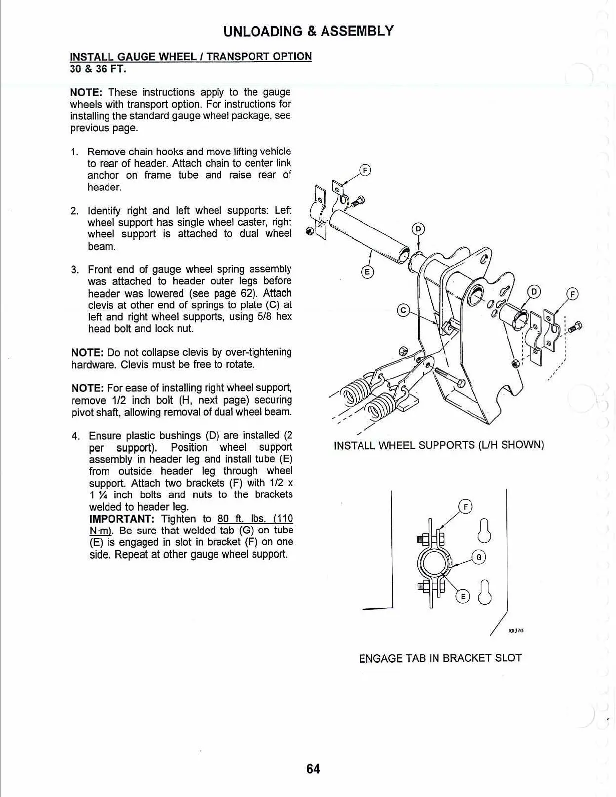
3.
Front end
of
gauge wheel spring assembly
was attached
to
header outer legs before
header
was
lowered
(see
page
62).
Attach
clevis
at
other
end
of
springs to plate (C)
at
left and right wheel supports, using 5/8 hex
head bolt and lock nut.
NOTE: Do not collapse clevis
by
over-tightening
hardware. Clevis must be free to rotate.
NOTE: For ease
of
installing right wheel support,
remove
1/2
inch bolt (H, next page) securing
pivot shaft, allowing removal
of
dual wheel beam.
4. Ensure plastic bushings (D) are installed
(2
per support). Position wheel support
assembly
in
header leg and install tube (E)
from outside
header
leg through wheel
support. Attach two brackets (F) with
1/2
x
1
X inch bolts and nuts to the brackets
welded to header leg.
IMPORTANT: Tighten to 80
ft.
lbs. (110
N
·m).
Be sure that welded tab (G) on tube
(E) is engaged
in
slot in bracket (F)
on
one
side. Repeat at
other
gauge wheel support.
64
INSTALL
WHEEL
SUPPORTS
(UH
SHOWN)
F
ENGAGE TAB
IN
BRACKET
SLOT