UNLOADING & ASSEMBLY
INSTALL
GAUGE
WHEEL
/ TRANSPORT OPTION
30
& 38 FT. (continued)
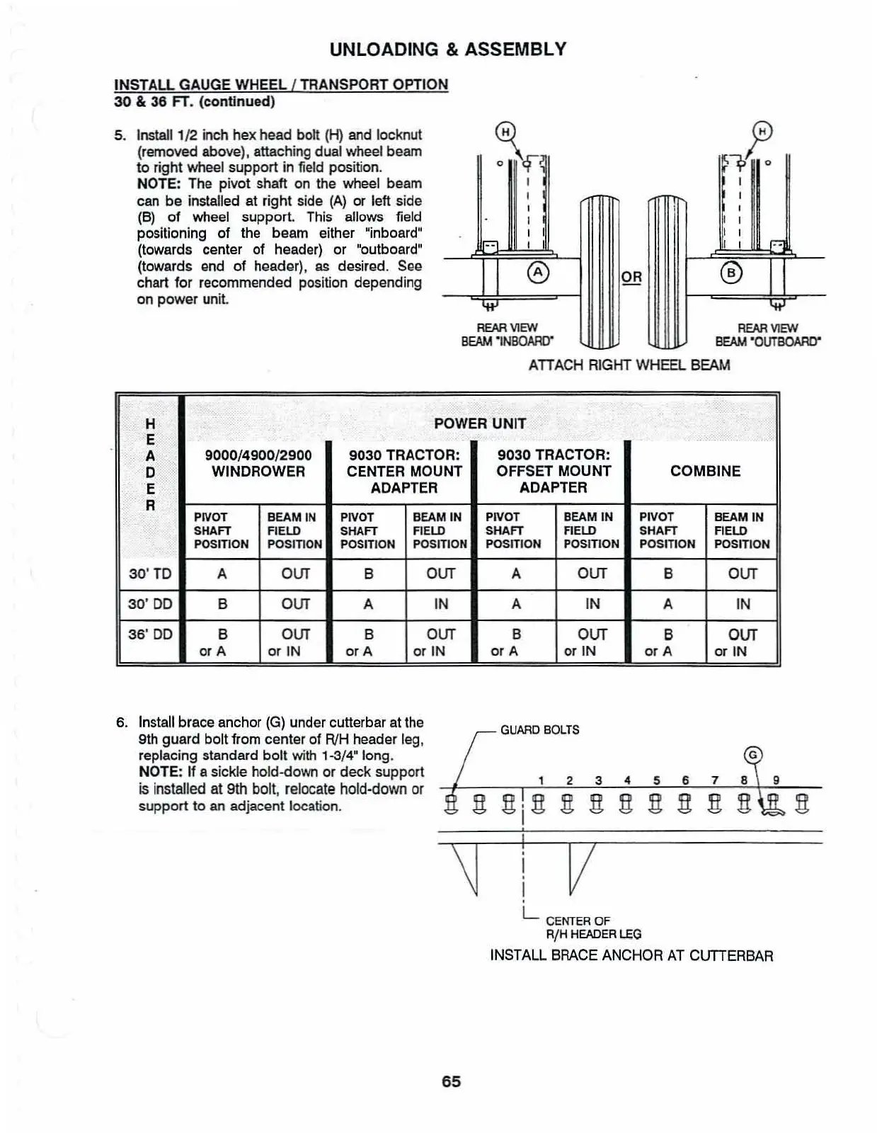
5.
Install1/2 inch hex head bolt
(H)
and locknut
(removed above), attaching dual wheel beam
to
right wheel support in field position.
NOTE: The pivot shaft on the wheel beam
can be installed at right side
(A)
or left side
(B)
of
wheel support. This allows field
positioning of the beam either "inboard"
(towards center of header) or ·outboard"
(towards
end
of header),
as
desired.
See
chart for recommended position depending
on power
unit
~
o
of
I
I
,
I
I
, I
....
....
REAR
VIEW
REAR
VIEW
BEAM
'INBOARD"'
BEAM
'OUTBOAAD"
ATIACH
RIGHT WHEEL BEAM
H
POWER
UNIT
E
A
9000/4900/2900
9030
TRACTOR:
9030
TRACTOR:
D
WINDROWER CENTER MOUNT
OFFSET
MOUNT
COMBINE
E
ADAPTER ADAPTER
R
PIVOT
BEAM
IN
PlVOT
BEAM
IN
PIVOT BEAM
IN
PIVOT
BEAM
IN
SHAFT
FIELD
SHAFT
FIELD
SHAFT
AELD
SHAFT
FIELD
POSITION POSITION
POSJTlON
POsmON
POSITION POSITION POSITION POSITION
30'TD
A
our
B
our
A
our
B
our
30'
DO
B
our
A IN A IN A IN
36'
DO
B
our
B
our
B
our
B
our
or
A
or
IN
mA
or IN
or
A
or
IN
or
A
or
IN
6.
Install brace anchor
(G)
under cutterbar at the
9th guard bolt
from center
of
RlH header leg,
replacing standard
bolt
with
1-3/4" long.
NOTE: If a sickle hold-down
or
deck
support
is
installed
at
9th
bolt,
relocate
hold-down
or
support
to an adjacent location.
65
GUARD
BOLTS
234567
v
L
CENTER
OF
R/H
HEADER
LEG
INSTALL BRACE ANCHOR
AT
ClITTERBAR