UNLOADING
&
ASSEMBLY
INSTAll.
GAUGE
WHEEL { TllANSPORT OPTlQN
30
&
36
FT.
(continued)
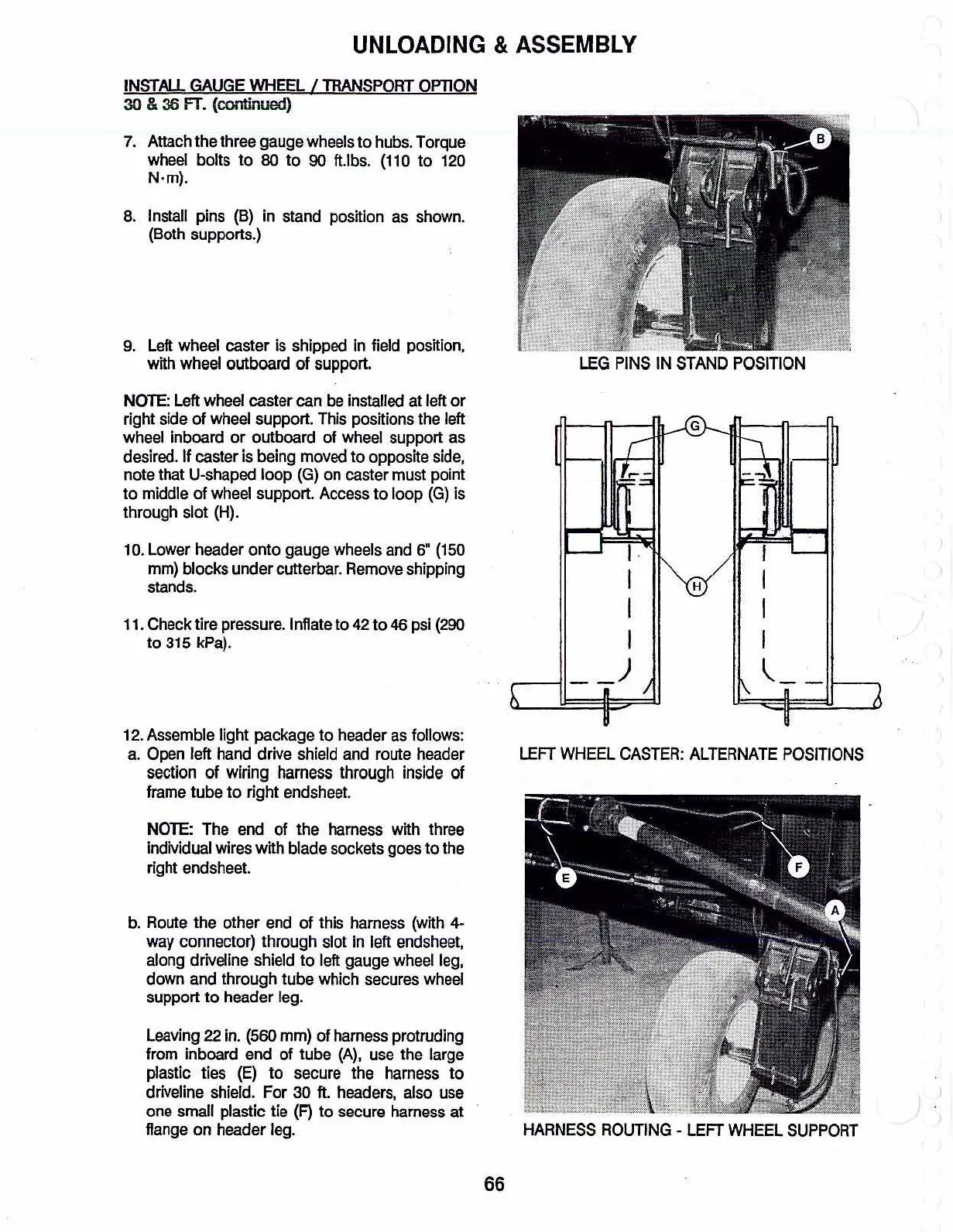
LEG
PINS
IN
STAND
POSITION
I
I
I
I
~
H
G
I
I
I
I
)
7.
Attach the three gauge wheels to hubs. Torque
wheel
bolts to
80
to
90
tUbs.
(110
to
120
N·m).
8.
Install pins
(B)
in stand position as shown.
(Both supports.)
9.
Left wheel caster
is
shipped
In
field position,
with
wheel
outboard
of
support.
NOTE:
Left
wheel caster
can
be installed at left or
right side of wheel support. This positions the left
wheel inboard
or
outboard of
wheel
support as
desired.
If
caster
is
being
moved
to
opposite
side,
note that U-shaped
loop
(G)
on caster must point
to
mlddle of wheel support. Access
to
loop
(G)
is
through slot (H).
11.
Check tire pressure. Inflate to
42
to
46
psi
(290
to
315 kPa).
1
a.lower
header
onto
gauge wheels and
6"
(150
mm)
blocks under cutterbar.
Remove
shipping
stands.
12. Assemble light package
to
header as follows:
a.
Open left hand drive shield and route header
section
of wiring
harness
through inside
of
frame tube
to
right endsheet.
NOTE:
The end
of
the harness with three
Individual wires with blade sockets goes
to
the
right endsheet.
b.
Route the other end of this harness (with 4-
way
connector) through slot in left endsheet,
along drivellne shield
to
left gauge wheel leg,
down and through tube which secures wheel
support
to
header leg.
leaving
22 in. (560 mm)
of
harness protruding
from inboard end
of
tube
(A),
use the large
plastlc ties
(E)
to
secure the harness
to
drlveline shield. For 30
ft.
headers, also use
one small plastic tie
(F)
to
secure harness at
flange
on
header leg.
LEFT
WHEEL
CASTER:
ALTERNATE
POSITIONS
HARNESS
ROUTING
-
LEFT
WHEEL
SUPPORT
66