OPERATOR’S STATION
Form 169017 45 Issue – June 2008
(continued next page)
L1 D130
DI
GNOST I C MODE?
L2 C140
NO / YES TR
CTOR SETUP?
L1 D 1 3 0
IEW ERROR CODES?
L2 C 1 4 0
NO/ YES ENTER SENSOR SETUP?
L1 D 1 3 0
IEW TR
CTOR CODES?
L2 C 1 4 0
NO / YES
IEW ENGINE CODES?
L1 1
1234 . 5 HRS 123
L2 E 4 7
SENSOR
OLTS LOW
L1 2
1234 . 5 HRS 123
L2 E 7 1
LOW HYDR
UL I C O I L
L1 D 1 3 0
E
IT TR
CTOR CODES?
L2 C 1 4 0
NO / YES
L1 D 1 3 0
IEW ENGINE CODES?
L2 C 1 4 0
NO / YES ENT ER SENSOR S E T U P ?
L1 1
1234 . 5 HRS 123
L2 4 4 9
FUEL PRESSURE H I GH
L1 D 1 3 0
E
I T ENG I NE CODES?
L2 C 1 4 0
NO / YES
L1 D 1 3 0
E
IT ERROR CODES?
L2 C 1 4 0
NO / YES
IEW TR
CTOR CODES ?
L1 D 1 3 0
ENTER SENSOR SETUP?
L2 C 1 4 0
NO/ YES RE
D SENSOR I NPUTS?
L1 D 1 3 0
KN I FE SPEED SENSOR
L2 C 1 4 0
EN
BLE / D I S
BLE
L1 D 1 3 0
REEL SPEED SENSOR
L2 C 1 4 0
EN
BLE / D I S
BLE
L1 D 1 3 0
HE
DER HT SENSOR
L2 C 1 4 0
EN
BLE / D I S
BLE
L1 D 1 3 0
HE
DER T I LT SENSOR
L2 C 1 4 0
EN
BLE / D I S
BLE
L1 D 1 3 0
HE
DER FLO
TSENSOR
L2 C 1 4 0
EN
BLE / D I S
BLE
L1 D 1 3 0
O
ERLO
D PRESSURE
L2 C 1 4 0
EN
BLE / D I S
BLE
L1 D 1 3 0
E
IT SENSOR SETUP?
L2 C 1 4 0
NO / YES KN I FE SPEED SENSOR
L1 D 1 3 0
RE
D SENSOR INPUTS?
L2 C 1 4 0
NO/ YES
CT I
TE FUNCT I ONS?
L1 D 1 3 0
SENSOR I NPUT
L2 C 1 4 0
HDR HE I GHT 3 . 5 9
L1 D 1 3 0
SENSOR I NPUT
L2 C 1 4 0
HDR
NGL E 1 . 8 4
L1 D 1 3 0
SENSOR I NPUT
L2 C 1 4 0
2.45
FLO
T2.84
L1 D 1 3 0
SENSOR I NPUT
L2 C 1 4 0
KN I FE SPEED 1 2 3 HZ
L1 D 1 3 0
SENSOR I NPUT
L2 C 1 4 0
REEL SPEED 12 3 HZ
L1 D 1 3 0
E
IT RE
DSENSORS?
L2 C 1 4 0
NO / YES SENSOR I NPU T
HDR HE I GHT 3 . 5 9
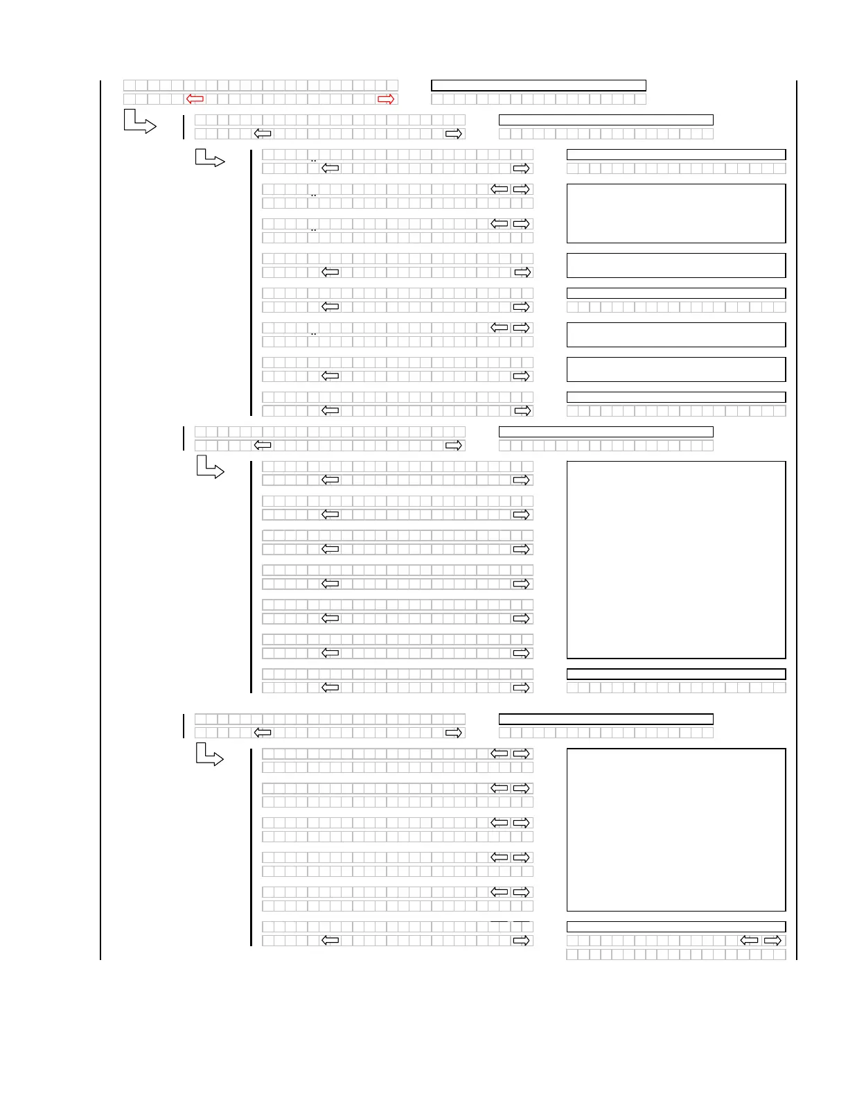
If "NO" then jump to:
If "NO" then jump to:
For diagnostic purposes each sensors input
signal can be read. This helps in determining
how each sensor is operating and if the proper
output voltages are being received by the control
system.
When "SELECT" is pressed the program goes to
the EXIT READ SENSORS? menu selection.
If "NO" then jump to:
The operator can select each sensor and
selectively enable or disable the sensor. This can
be used to disable a failed sensor to eliminate
false or erratic display readings.
When "SELECT" is pressed the program goes to
the EXIT SENSOR SETUP? menu selection.
If "NO" then jump to:
If "NO" then jump to:
The last 10 distinct error codes are stored.
If "NO" then jump to the first engine error code
logged.
If "NO" then jump to:
If "NO" then jump to:
If "NO" then jump to:
The last 10 distinct error codes are stored along
with the code #, Exxx, engine hours and number
of occurrences. The "arrow" keys are used to
cycle between codes.
If "NO" then jump to the first error code logged.
If "NO" then jump to: