3 - 40
Ü
OCCASIONAL MAINTENANCE
REPLACE Wheels
For this operation, we recommend using the hydraulic jack MANITOU reference 505507
and the safety support MANITOU reference 554772.
t
IMPORTANT
t
In the event of a wheel being changed on the road, secure the environment of the lift truck:
- If possible, stop the lift truck on even and hard ground.
- Shut down the lift truck (e 1 - OPERATING AND SAFETY INSTRUCTIONS: DRIVING
INSTRUCTIONS UNLADEN AND LADEN).
- Turn on the emergency lights.
- Apply wedges to immobilise the lift truck in both directions on the axle opposite
to the wheel to be changed.
- Unlock the nuts of the wheel to be changed.
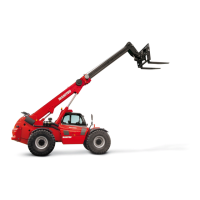
- Place the jack under the flared axle tube, as near as possible to the wheel and
adjust the jack.
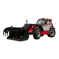
- Lift the wheel until it comes off the ground and put in place the safety support
under the axle.
- Completely unscrew the wheel nuts and remove them.
- Free the wheel by reciprocating movements and roll it to the side.
- Slip the new wheel on the wheel hub.
- Refit the nuts by hand, if necessary grease them.
- Remove the safety support and lower the lift truck with the jack.
- Tighten the wheel nuts with a torque wrench (e 2000 HOUR - PERIODIC
MAINTENANCE - EVERY 2000 HOURS OF SERVICE OR 4 YEARS) for tightening torque.
ADJUST Front headlights
RECOMMENDATIONS FOR ADJUSTMENT
(as per standard ECE-76/756 76/761 ECE20)
Set to -2% of the dipped beam in relation to the horizontal line of
the headlamp.
ADJUSTING PROCEDURE
- Place the lift truck unladen and in the transport position, and
perpendicular to a white wall on flat, level ground.
- Check the tyre pressure (
e 2 - DESCRIPTION: TYRES).
- Position the gear selector to neutral.
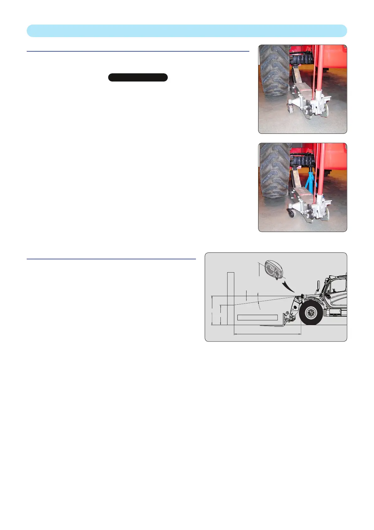
CALCULATION OF DIPPED BEAM HEIGHT (H2)
•
h1 = Height of the low beams in relation to the ground.
• h2 = Height of the adjusted beam.
• l= Distance between the low beams and the white wall.
+%
-%
l
h1
h2
-2%
h2 = h1 - (l x 2 / 100)
h1
649100 EN-US-AU (20/05/2019)
MLT 961-145 V PLUS L JD ST4 S1
 Loading...