Grove Published 3-23-2020, Control # 654-04 5-25
GRT655/655L OPERATOR MANUAL SET-UP AND INSTALLATION
Erecting
Tools required:
• 1/2 in Impact Wrench
• 24 in - 1/2 in Drive Impact Extension (p/n 80104116)
• 1/2 in Square Drive Socket - 1/2 in Square Nut
(80104383)
NOTE: Refer to Figure 5-16 for an illustration of the boom
extension.
1. Fully extend and set the outriggers using normal setup
procedures (refer to “Setting the Outriggers” on
page 25).
2. If extended, fully retract all of the boom sections.
3. Set boom angle to 0° (zero degrees).
NOTE: The auxiliary boom nose (rooster sheave) does not
have to be removed. However, if reeved, the hoist
rope must be removed from the sheave.
4. Rig either the main hoist or optional auxiliary hoist rope
for single part line with only the wedge socket on the end
of the hoist rope.
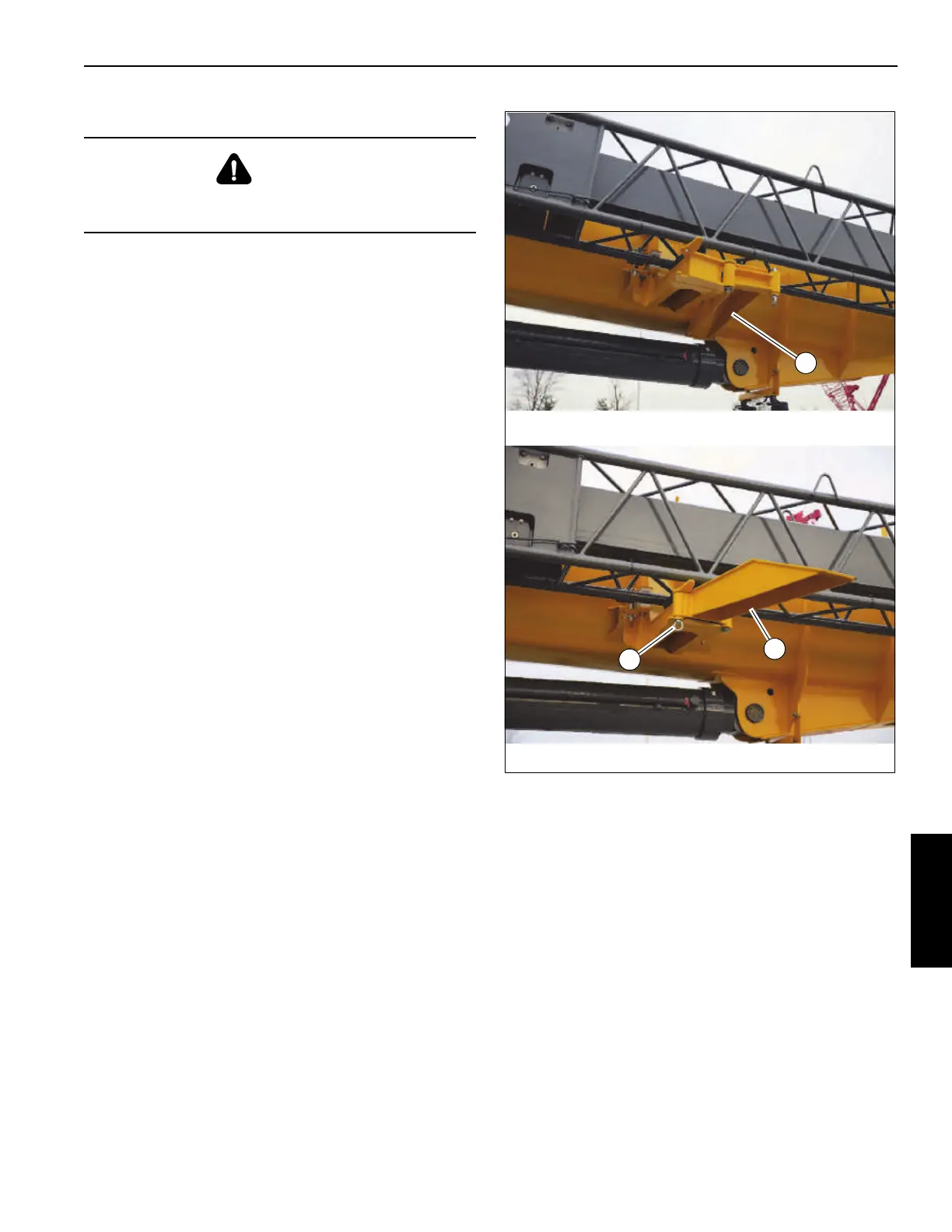
5. Fold out the ramp (1, Figure 5-17) at the rear stowage
bracket. Secure in place with spring-locking pin
(2, Figure 5-17).
DANGER
To prevent serious injury or death, do not stand on crane
decking unless boom extension is secure.
FIGURE 5-17
1
9216-10
9216-1
1
2
 Loading...


