Grove Published 3-23-2020, Control # 654-04 5-33
GRT655/655L OPERATOR MANUAL SET-UP AND INSTALLATION
c. Slowly lower the boom until the boom extension tip
is resting on the ground and pressure is relieved
from the offset links.
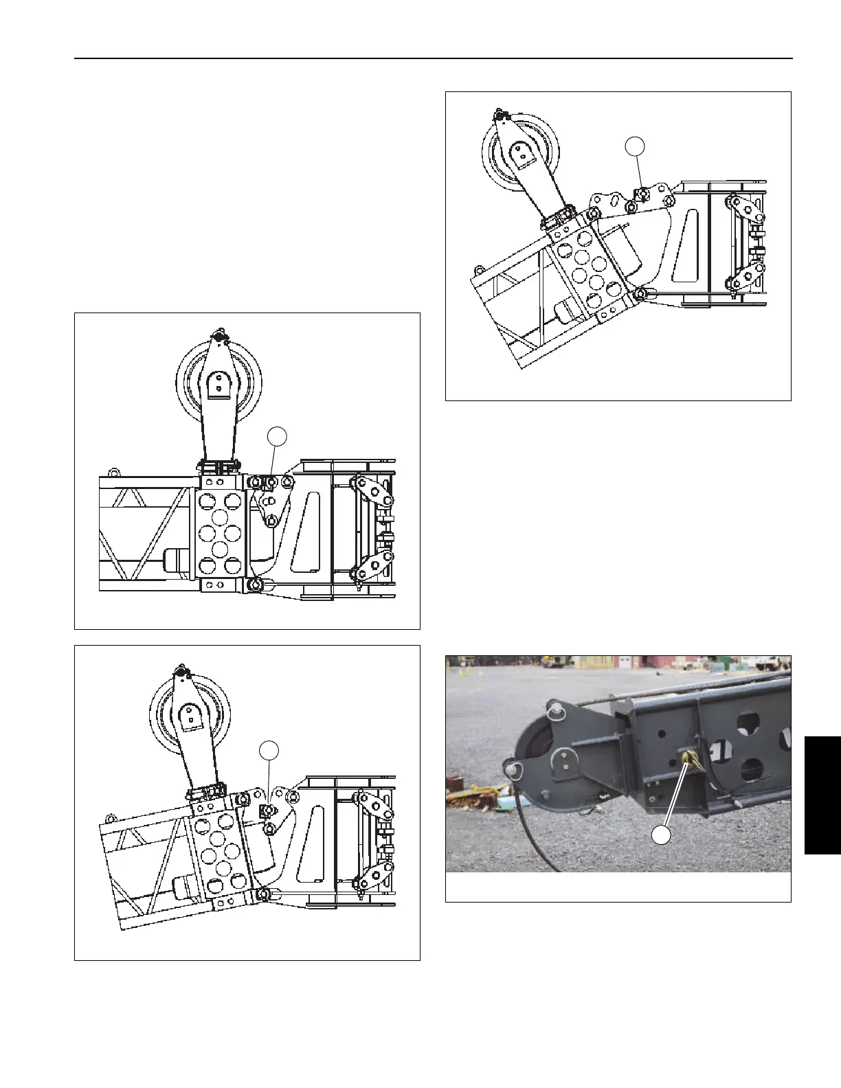
d. Remove the offset link retaining clips and
attachment pins and lower the boom until the holes
for the lesser degree offset position align in the
offset links. Install the offset attachment pins and
retaining clips (Figure 5-35 through Figure 5-37).
e. Slowly elevate the boom until the offset links take
the full weight of the boom extension.
f. Reeve the hoist rope as described under normal
erecting procedures.
Extending and Stowing the Telescoping
Boom Extension Fly Section
Extending
1. Extend and set the outriggers and swing the boom to
over the front.
2. Lower the boom to below horizontal.
3. Disconnect the stinger anti-two block cable end
connector from the anti-two block switch and secure it in
the stowage clip.
4. Remove the pin (1, Figure 5-38) securing the
telescoping section to the base section.
5. Pull the telescoping section out of the base section until
the holes in the rear of the telescoping section align with
the holes in the tip of the base section.
FIGURE 5-35
8999-3
1
0° Offset
Attachment Pin
Location
FIGURE 5-36
8999-1
2
15° Offset
Attachment Pin
Location
FIGURE 5-37
8999-2
3
30° Offset
Attachment Pin
Location
 Loading...


