Grove Published 3-23-2020, Control # 654-04 3-9
GRT655/655L OPERATOR MANUAL OPERATING CONTROLS
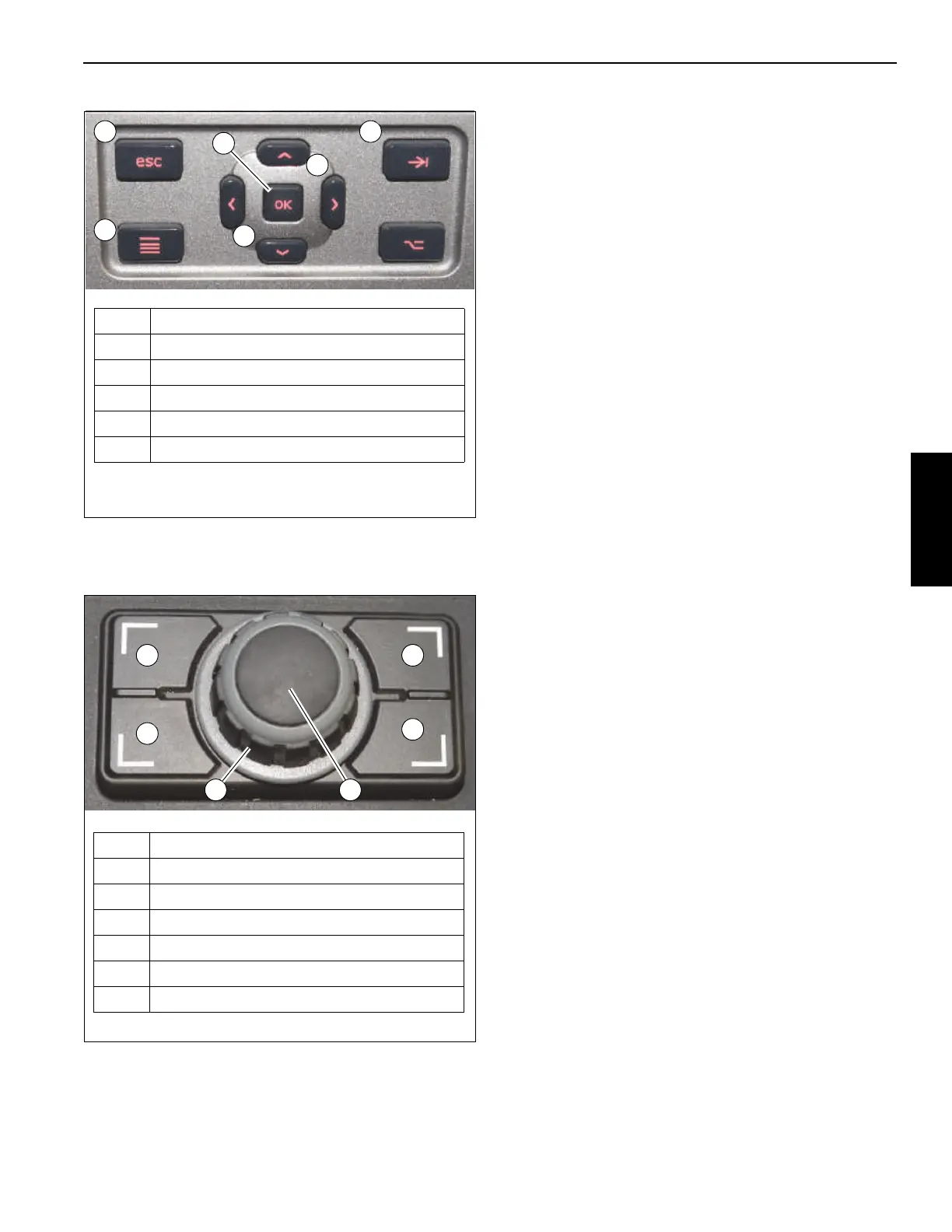
The Jog Dial (Figure 3-7), mounted on the right armrest (see
Jog Dial, page 3-12), can be used to navigate the two
modules in a similar manner as the Navigation Control Pads.
Refer to Navigating the Operator Display Module and Rated
Capacity Limiter Display Module, page 4-34 for information
on how the Navigational Controls Pads and Jog Dial are
used in the operation of the crane.
USB Connector
A USB Connector is provided (4, Figure 3-5) for the Rated
Capacity Limiter Display Module (RDM) and the Operator
Display Module (ODM). Each USB Connector is located
immediately below and to the left of its related display
module screen.
The USB Connector allows a service technician to connect
to the display module and update its software or download
the data logger, which records certain events that can occur
when operating the crane.
RCL Shutdown Warning Indicator (Non-CE
Certified Cranes)
The RCL Shutdown Warning Indicator (5, Figure 3-5) is
located immediately below and to the right of the Rated
Capacity Limiter Display Module (RDM) screen.
The RCL Shutdown Warning Indicator comes on (red) when
the RCL senses a lift that is greater than 100% of capacity for
the programmed crane configuration. When the RCL senses
a lift that is greater than 100% of capacity, the Crane Control
System (CCS) will lockout the boom up/down, telescope
extend, and hoist up crane functions, which would worsen
the overload condition.
If the load is greater than 100% of capacity, overriding the
crane function lockouts is accomplished using either the
Limit Bypass Switch (Front Limit Bypass Switch (Non-CE
Certified Cranes), page 3-14) or the Limit Bypass Switch
(Rear Limit Bypass Switch (Non-CE Certified Cranes),
page 3-19).
RCL Shutdown Warning Indicator (CE
Certified Cranes)
The RCL Shutdown Warning Indicator (5, Figure 3-5) is
located immediately below and to the right of the Rated
Capacity Limiter Display Module (RDM) screen.
The RCL Shutdown Warning Indicator comes on (red) when
the RCL senses a lift that is between 100% to 110% of
capacity for the programmed crane configuration. When the
RCL senses a lift between 100% to 110% of capacity, the
crane control system will lockout the boom up/down,
telescope extend, and hoist up crane functions, which would
worsen the overload condition.
If the load is between 100% to 110% of capacity, overriding
the crane function lockouts is accomplished using the Limit
Bypass Set-up Switch (refer to Limit Bypass Set-Up Switch
(CE Certified Cranes), page 3-15). If the load is greater than
110% of capacity, overriding the crane function lockouts is
accomplished using the Limit Bypass Bridging Switch (refer
to Bridging Switch and Indicator (CE Certified Cranes),
page 3-20).
Item Description
1 Escape Button
2 Tab Button
3 Menu Button
4 Left/Right/Up/Down Arrow Buttons
5 OK Button
FIGURE 3-6
1 2
4
3
4
5
9221-1
FIGURE 3-7
Item Description
1 Escape Button
2 Tab Button
3 Screen Toggle Button
4 Menu Button
5 Jog Dial (Rotate dial to move cursor)
6 OK Button (Press Jog Dial to select)
9221-2
1 2
3
4
5 6
 Loading...


