Grove Published 3-23-2020, Control # 654-04 6-35
GRT655/655L OPERATOR MANUAL LUBRICATION AND MAINTENANCE
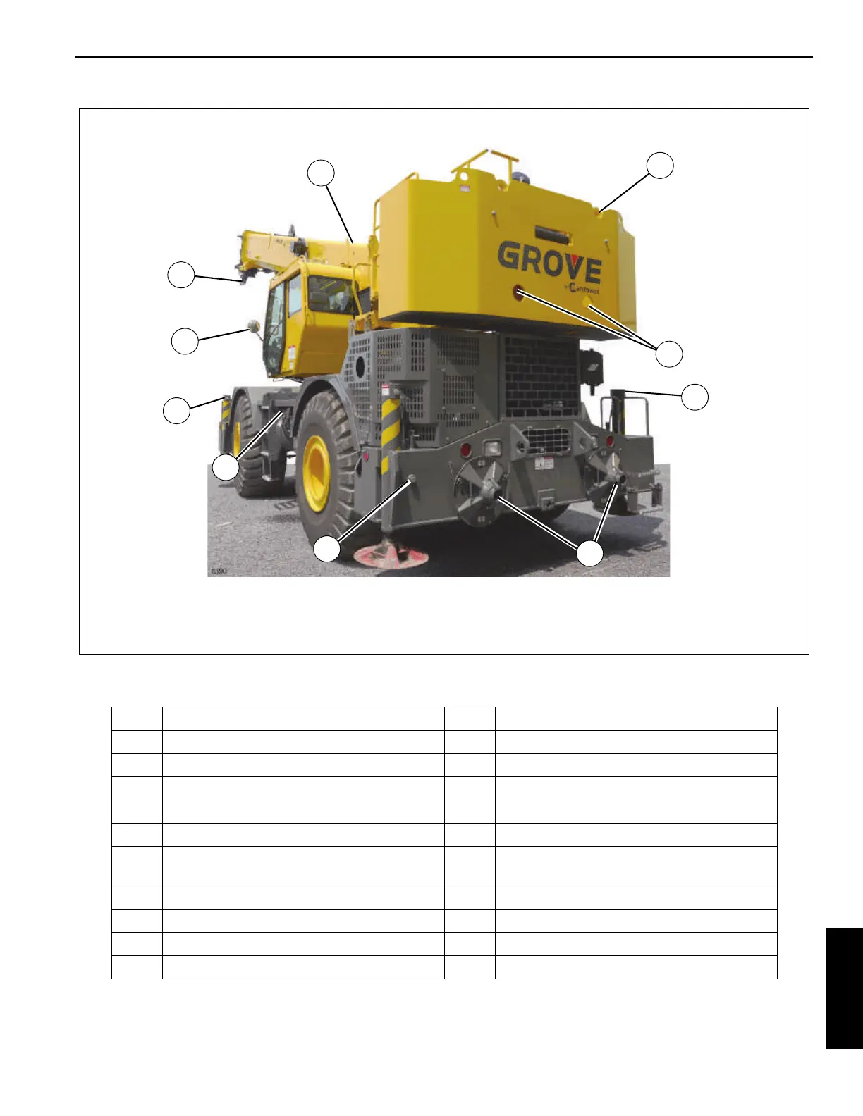
TABLE 6-1. Rust Inhibitor Application Locations
Figure 6-17
Picture may not be same model as your
machine, it is for reference only.
19
21
3
20
9
11
12
9
22
7
1 Pivot Shaft 12 O/R Beam Wear Pad Adjustment Hardware
2 Boom Extension Pins, Clips 13 Entire underside of unit
3 Boom Nose Pins, Clips 14 Powertrain Hardware Inside Compartment
4 Hook Block/Overhaul Ball 15 Valve Bank
5 Boom Extension Hanger Hardware 16 Hoist Hose Connections
6 Hose Connections inside turntable 17 Tension Spring
7
All Hardware, Clips, Pins, Hose Connections
not painted O/R Pins, Clips
18 Wire Rope
8 Turntable Bearing Fasteners 19 Counterweight Mounting Hardware
9 O/R Hose Connections 20 Counterweight Pins
10 Hook Block Tiedown Cable 21 Hose Connections
11 O/R Pins, Clips 22 Mirror Mounting Hardware
 Loading...


