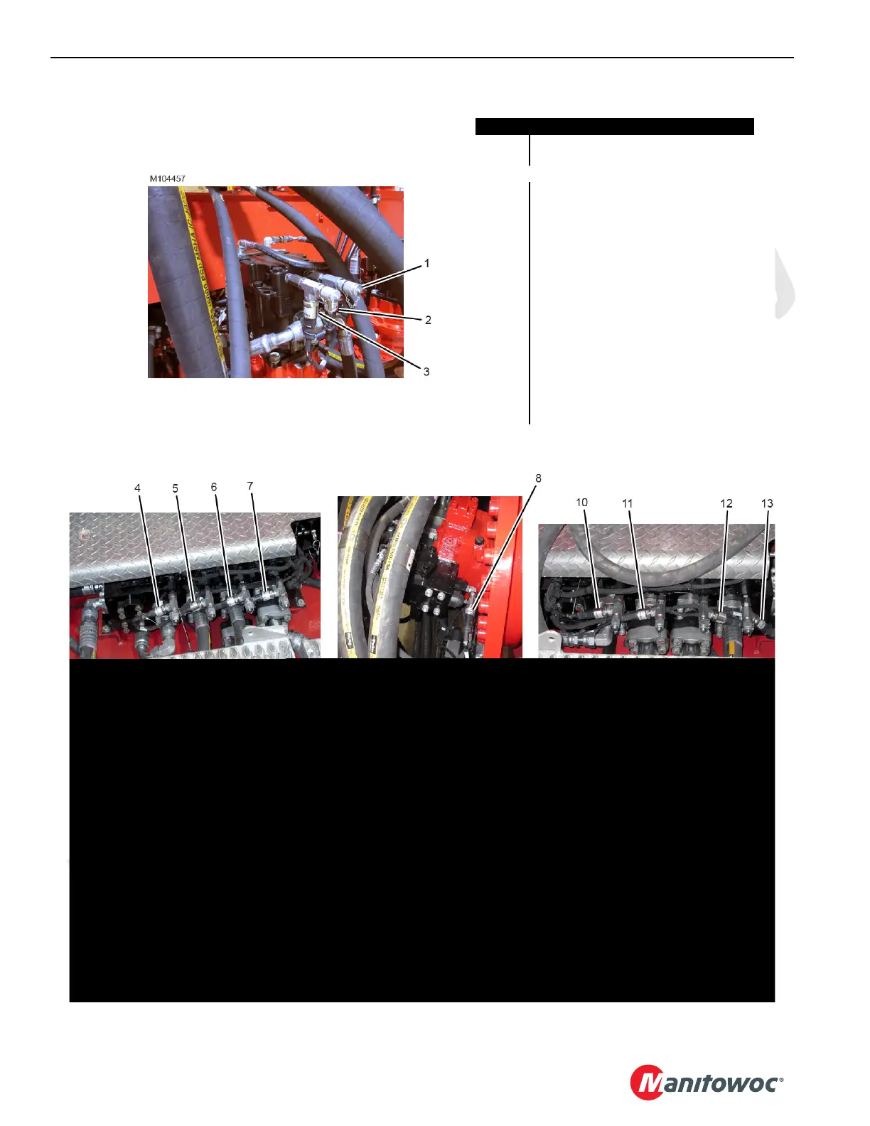
FIGURE 2-23
Front of Rotating Bed
Left Inboard Side of Rotating Bed
Right Inboard Side of Rotating Bed
Typical at Drums 4 and 6
Right Inboard Side of Rotating Bed
Under Rear of Rotating Bed
Item Description
1 Gauge Coupler with Dust Cap
-18 UNF x -6
PRESSURE TRANSDUCER ID
2 Swing Right
3 Swing Left
4 Accessory System 1
(see Main Display Operation Manual)
5Drum 4
6 Drum 5 (not used)
7 Left Travel
8 Typical Drum 4 or 6
9 Typical Pump 1, 2, 3, or 4
10 Drum 4
11 Right Travel
12 Drum 6
13 Accessory System 2
(see Main Display Operation Manual)
14 Fan Motor

 Loading...


