Manitowoc Published 11-22-17, Control # 257-02 10-17
MLC300 SERVICE/MAINTENANCE MANUAL ACCESSORIES
10
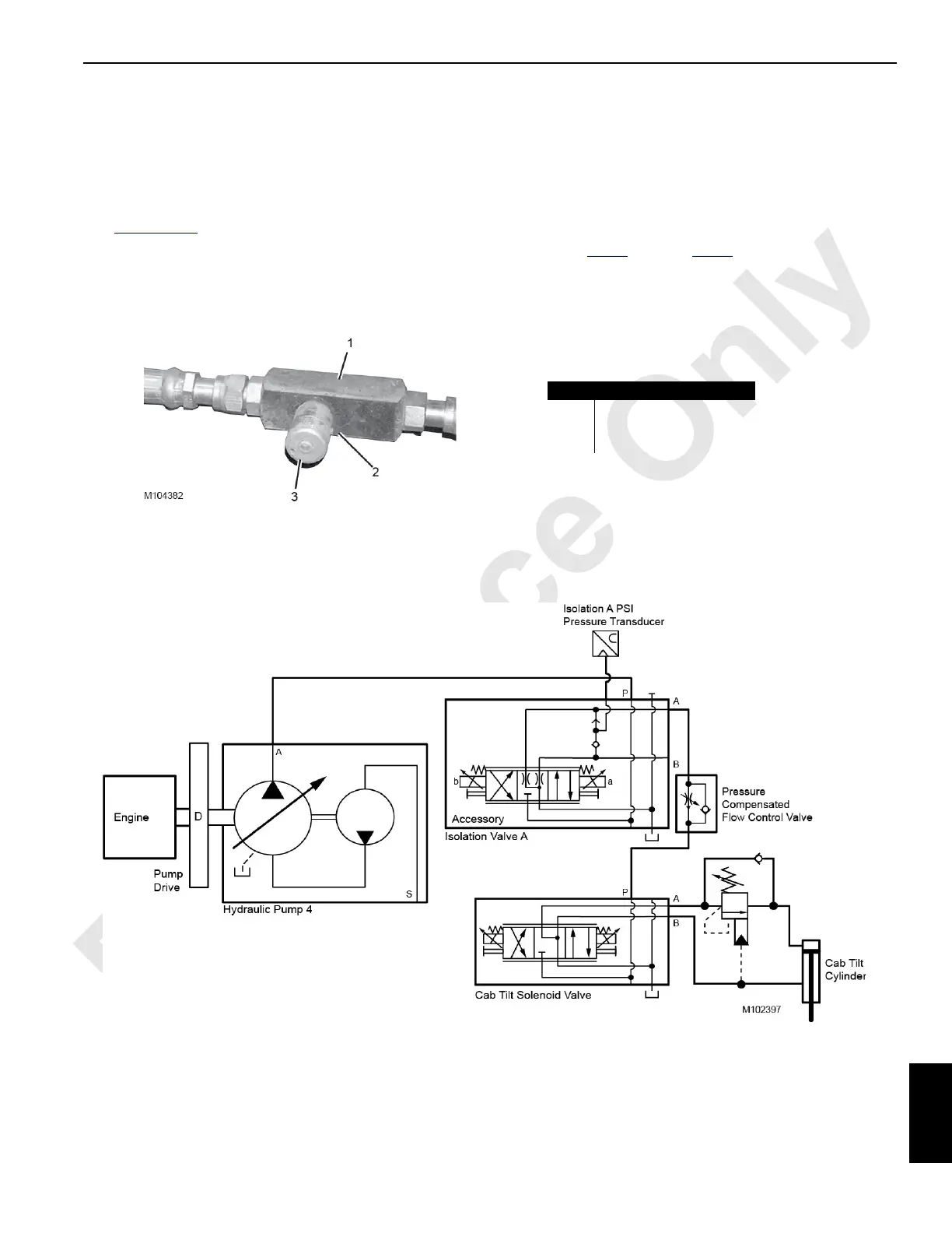
Cab Tilt Adjustment
The cab tilt circuit contains a pressure-compensated flow
control valve (1) that allows adjustment of the cab tilt speed.
The flow control valve is located near the cab, on the left side
of the rotating bed.
See Figure 10-11
for the following procedure.
To adjust the speed at which the cab tilts up and down,
perform the following.
1. Loosen the set screw (2).
2. Turn the adjusting knob (3) clockwise to close the valve.
3. Open the valve slightly by turning the adjusting knob
counterclockwise.
4. Test the cab tilt operation using the S23 cab tilt switch on
the cab control console.
5. Repeat step 2
through step 4 until cab tilt starts and
stops smoothly.
6. Securely tighten the set screw.
Cab Tilt Hydraulic Schematic
Item Description
1 Flow Control Valve
2Set Screw
3 Adjusting Knob
FIGURE 10-11
 Loading...


