Manitowoc Published 11-22-17, Control # 257-02 2-21
MLC300 SERVICE/MAINTENANCE MANUAL HYDRAULIC SYSTEM
Filter 1
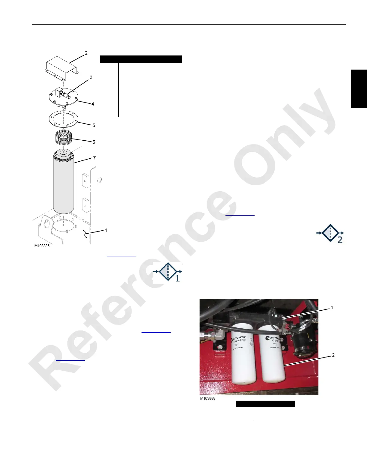
An in-tank filter—Filter 1 (see Figure 2-17)—filters return oil.
Replace the filter element when the fault alarm
comes on and the Filter 1 icon appears in the
Fault Bar of the main display.
Replace the filter element at each oil change
interval, also.
NOTE: It is normal for the fault alarm to come on at startup
when the oil is cold. The fault alarm should turn off
after the hydraulic oil warms up.
To replace Filter 1, proceed as follows (see Figure 2-17
).
1. Stop the engine.
2. Vent the hydraulic tank using either of the vent valves
(see Figure 2-15
).
3. Take precautions to prevent being burned by hot oil.
4. Remove the guard (2).
5. Disconnect the electric cable from the pressure
switch (3).
6. Clean the cover (4) and the area around the filter cover.
Do not allow contaminants to enter the hydraulic tank.
7. Remove the lock nuts and washers and remove the
cover.
8. Remove the spring (6).
9. Lift the filter element (7) out of the hydraulic tank using
the handle provided and discard it according to local
environmental regulations.
10. Install a new filter element so it is fully seated in the
hydraulic tank.
11. Replace the gasket (5) with a new one.
12. Install the cover.
13. Connect the electric cable to the pressure switch.
14. Install the guard.
15. Start the engine and allow the hydraulic system to reach
its normal operating temperature.
16. Check the filter cover for leaks and service as required.
17. Stop the engine.
18. Check the hydraulic tank level and fill as required.
Filter 2
Filter 2 (see Figure 2-18) filters the oil to the cooler circuit.
Replace both filter elements when the fault
alarm comes on and the Filter 2 icon appears
in the Fault Bar of the main display.
Replace both filter elements at each oil change
interval, also.
NOTE: It is normal for the fault alarm to come on at startup
when the oil is cold. The fault alarm should turn off
after the hydraulic oil warms up.
Item Description
1 Hydraulic Tank
2 Guard
3 Pressure Switch
4 Cover (with lock nuts and
flat washers)
5 Gasket
6Spring
7 Filter Element with Handle
FIGURE 2-17
FIGURE 2-18
Item Description
1 Filter Head
2Filter Element
Below Engine on Right Inboard Side of Rotating Bed

 Loading...


