Manitowoc Published 11-22-17, Control # 257-02 7-5
MLC300 SERVICE/MAINTENANCE MANUAL POWER TRAIN
ENGINE CONTROLS
See the engine start procedure in Section 3 of the MLC300
Operator Manual for engine startup. See the Cummins
engine manual for detailed engine instructions.
The engine is started and stopped with the engine key
switch.
The speed of the crane motors and actuating cylinders
depends on engine speed and equipment control handle
movement. Engine speed is controlled with the hand or foot
throttle. Node 1 controller and engine node 0 controller
process and control engine information, which is shown on
the main display.
The emergency stop push button stops the engine in an
emergency. All brakes apply, and any functions stop
abruptly.
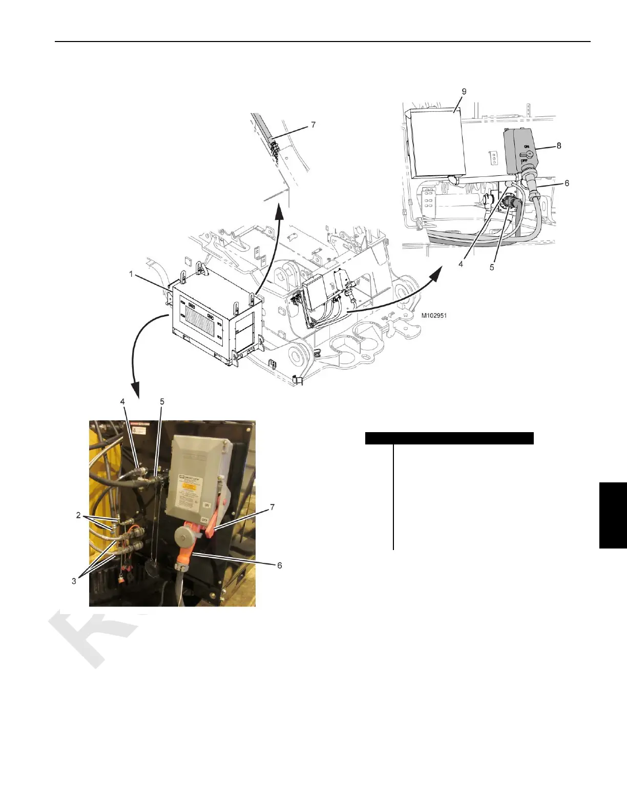
Item Description
1 Auxiliary Power Unit
2 Air Conditioner Hose (qty 2)
3 Fuel Hose (qty 2)
4 Electric Cable (DC, WAC1)
5 Electric Cable (DC, WAD1)
6 Power Supply Cable (AC, WAA1)
7 Interlock Switch
8
Interlock Switch
9
Load Center
FIGURE 7-4
 Loading...


