Manitowoc Published 11-22-17, Control # 257-02 3-11
MLC300 SERVICE/MAINTENANCE MANUAL ELECTRICAL SYSTEM
Control Modules
Control modules perform several functions:
• Run the software control programs
• Communicate with each other over the CAN Bus
• Read input devices
• Command output devices
Control Module Naming Conventions
There are three types of control modules in the CAN Bus
system:
• Safety Control Module (SCM)
• Crane Control Module (CCM)
• Input/Output—Large (IOL)
• Input/Output—Small (IOS)
Control modules are named in the format MWXXXABC.
Table 3-2
defines the variables used to build the name.
Table 3-2. Control Module Naming Definitions
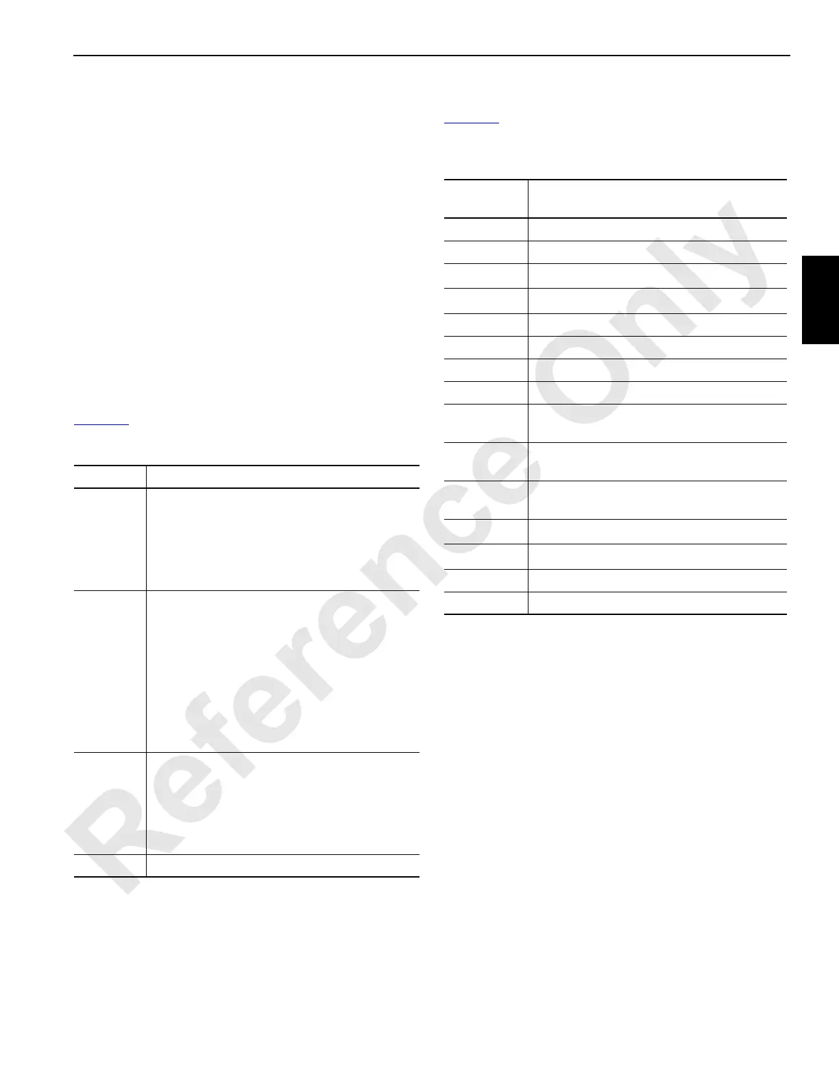
Control Module Input/Output (I/O) Types
Table 3-3 defines the terms used in the schematics for the I/
O types used by the control modules.
Table 3-3. Control Module I/O Types
Identifier Definition
XXX
Module Type:
SCM
CCM
IOL
IOS
A
CAN Bus ID:
- = Multiple Buses
A = CAN Bus A
B = CAN Bus B
C = CAN Bus C
D = CAN Bus D
J = CAN Bus J
H = CAN Bus H
B
Module Hardware ID:
0 = SCM
1 = CCM
2 = IOS
3 = IOL
C Module Index
Schematic
Term
Definition
IAC Analog Current Input
IACV Analog Current/Voltage Input
IBRTC
n
IN Battery RTC Negative Input
IBRTC
p
IN Battery RTC Positive Input
ID Digital Input
IDF Digital Frequency Input
IMID1 Module Identifier Input
KL15 Key Switch Power
ODHxA
Digital Output, where “x” is the current in
Amps
OPHxA
PWM Output High Side, where “x” is the
current in Amps
OPLxA
PWM Output Low Side, where “x” is the
current in Amps
OS85H
8.5 V
DC
Supply Power
OS85L
8.5 V
DC
Supply Ground
+UB Battery Supply
+UE Electronic Supply

 Loading...


