Manitowoc Published 11-22-17, Control # 257-02 3-5
MLC300 SERVICE/MAINTENANCE MANUAL ELECTRICAL SYSTEM
CIRCUIT BREAKERS, FUSES, AND RELAYS
Most circuit breakers, fuses, and relays are located in the DC
load center junction box (see Figure 3-4
).
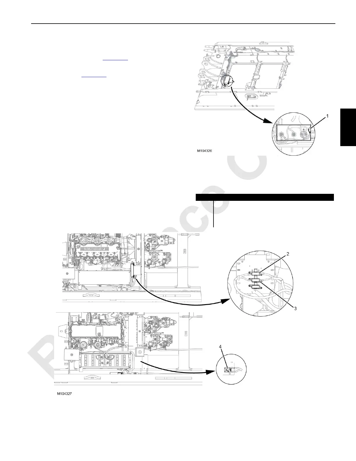
The following fuses and circuit breaker are not located in the
DC load center (see Figure 3-3
):
• TCU CraneStar 5 A fuse F5 (1)—Fuse F5 is mounted on
the battery disconnect switch bracket.
• Alternator 150 A fuse F0 (2) (Cummins engine)—Fuse
F0 is mounted on a panel at the front of the battery box.
• Alternator 150 A circuit breaker CB0 (4) (MTU engine)—
Circuit breaker CB0 is mounted on a panel at the right
side of the battery box.
• Intake air heater 150 A fuse F6 (3) (Cummins engine)—
Fuse F6 is mounted on a panel at the front of the battery
box.
FIGURE 3-3 continued
Item Description
1 CraneStar 5 A Fuse (F5)
2 Alternator 150 A Fuse (F0) (Cummins engine)
3 Intake Air Heater 150 A Fuse (F6) (Cummins engine)
4 Alternator 150 A Circuit Breaker (CB0) (MTU engine)
Cummins Engine
MTU Engine
 Loading...


