HYDRAULIC SYSTEM MLC300 SERVICE/MAINTENANCE MANUAL
2-30
Published 11-22-17, Control # 257-02
HYDRAULIC TESTS AND CALIBRATIONS
Only experienced technicians trained in the operation of this
crane and its hydraulic system shall perform the procedures
described in this section. The technicians shall read,
understand, and comply with the instructions in this section
and the instructions in the MLC300 Main Display Operation
Manual.
Contact your Manitowoc Cranes dealer for an explanation of
any procedure not fully understood.
The calibration and test procedures described in this section
were performed before the crane shipped from the factory.
These procedures must be performed by field personnel only
when parts are replaced or when instructed by a Manitowoc
Cranes dealer.
Pressure Sender Calibration
See the MLC300 Main Display Operation Manual.
Controls Calibration
See the MLC300 Main Display Operation Manual.
Charge Pressure Test
See the MLC300 Main Display Operation Manual.
High Pressure Test
See the MLC300 Main Display Operation Manual.
Travel Speed Test
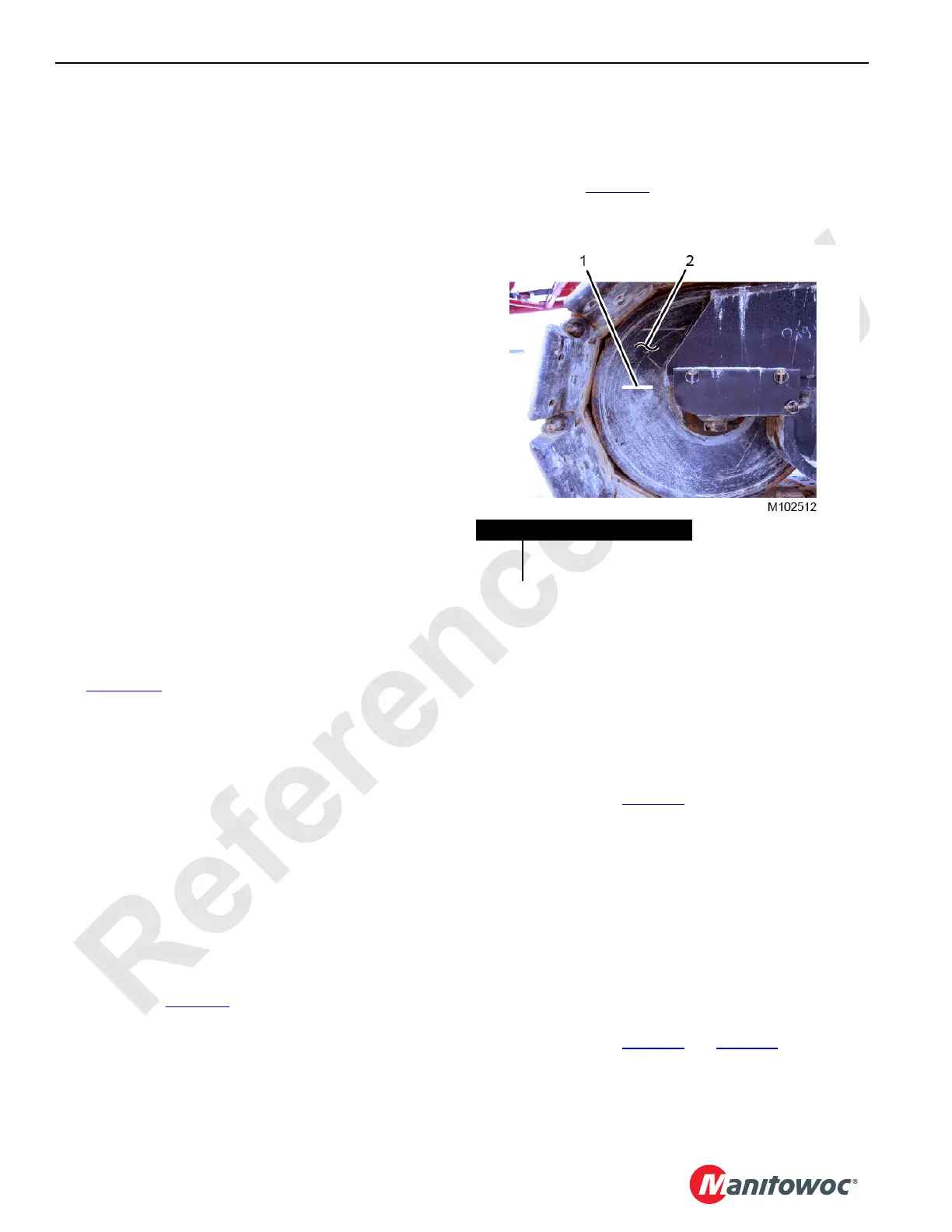
See Figure 2-25 for the following procedure.
NOTE: Perform this test in an area where the crane can
travel without interference.
An assistant is needed to count the rotations of the
crawler rollers.
1. Apply a timing mark (1) on the inside faces of the front
crawler rollers (2).
2. Start the engine and run it at high idle.
3. Using the travel speed selection switch, select high
speed travel.
4. Travel the crane forward at full speed for one minute
while the assistant walks alongside the crane and
counts the timing mark revolutions.
5. Verify the counted revolutions are within the limits
specified in Table 2-2
. If the counted rotations are not
within the specified range, contact the Manitowoc Crane
Care Lattice Team.
6. Travel the crane in reverse at full speed for one minute
while the assistant walks alongside the crane and
counts the timing mark revolutions.
7. Verify the counted revolutions are within the limits
specified in Table 2-2
. If the counted rotations are not
within the specified range, contact the Manitowoc Crane
Care Lattice Team.
Swing Speed Test
NOTE: Perform this test in an area where the crane can
swing without interference.
1. Navigate to the Swing Control Information screen in the
main display.
2. Start the engine and run it at high idle.
3. Operate the swing fully left and then fully right.
4. Verify that the swing speed shown in the main display is
within the limits in Table 2-1
.
Drum Speed Test
NOTE: Perform this test in an area where the crane can
operate without interference.
1. Navigate to the Drum Control Information screen (Drum
1, 2, 3, 4, 5, or 6) in the main display.
2. Start the engine and run it at high idle.
3. Move the selected drum handle fully forward and then
fully back.
4. Verify that the drum speed shown in the main display is
within the limits in Table 2-1
and Table 2-2.
FIGURE 2-25
Item Description
1 Timing Mark
2 Front Crawler Roller (qty 2)

 Loading...


