SWING SYSTEM MLC300 SERVICE/MAINTENANCE MANUAL
6-6
Published 11-22-17, Control # 257-02
SWING BRAKE MANUAL RELEASE
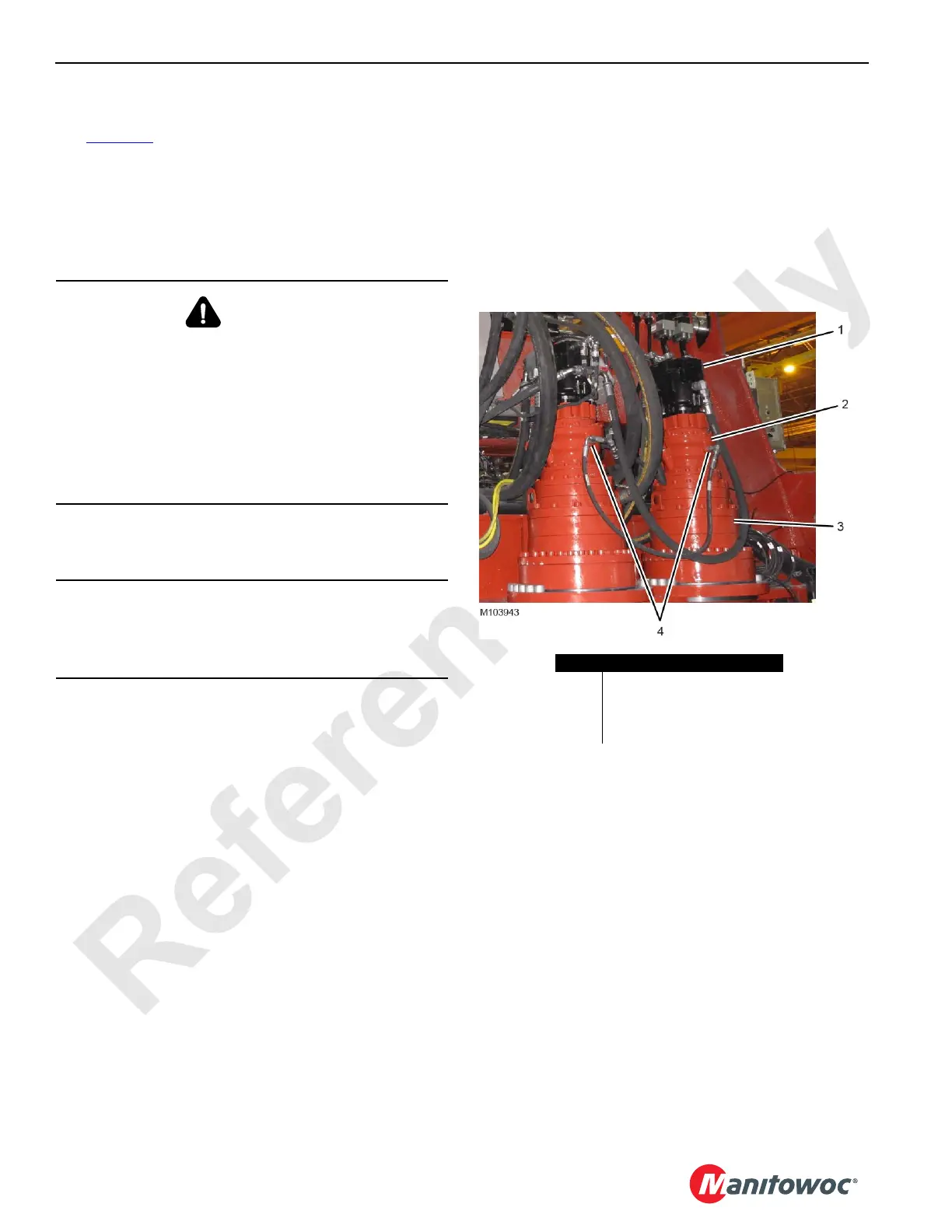
See Figure 6-4 for the following procedure.
Depending on your options, the crane has either one or two
swing drives.
When removing or installing the swing drive, the swing brake
must be released to allow alignment of the swing pinion with
the slewing ring gear.
NOTE: A hydraulic hand pump with a pressure gauge is
needed to manually release the swing brake.
1. Disconnect the existing brake hose and fittings from the
adapter fitting in the brake release port (4).
2. Connect the hand pump hose to the adapter fitting with
user-supplied 06 ORFS fittings.
3. To release the brake, pressurize it to 21 bar (300 psi)
with the hydraulic hand pump.
4. Service the swing drive as required.
5. At the completion of servicing, perform the following
procedure.
a. Apply the swing brake by relieving the pressure with
the hand pump.
b. Disconnect the hand pump hose from the adapter
fitting in the brake release port.
c. Connect the existing brake hose and fittings to the
adapter fitting in the brake release port.
WARNING
Unexpected Crane Movement!
When the swing brake is released, the crane can
suddenly swing. Before releasing the swing brake, secure
the crane by lowering the boom onto blocking at ground
level to prevent sudden uncontrolled swinging.
The swing brake manual release procedure is for
servicing purposes only. Do not operate the crane unless
the swing brake is fully operational.
CAUTION
Avoid Damage to Parts!
When releasing the swing brake with the hand pump, do
not exceed 21 bar (300 psi) of pressure.
Item Description
1Swing Motor
2 Swing Brake Release Port
3 Swing Gearbox
4 Brake Release Port
FIGURE 6-4
 Loading...


