ACCESSORIES MLC300 SERVICE/MAINTENANCE MANUAL
10-2
Published 11-22-17, Control # 257-02
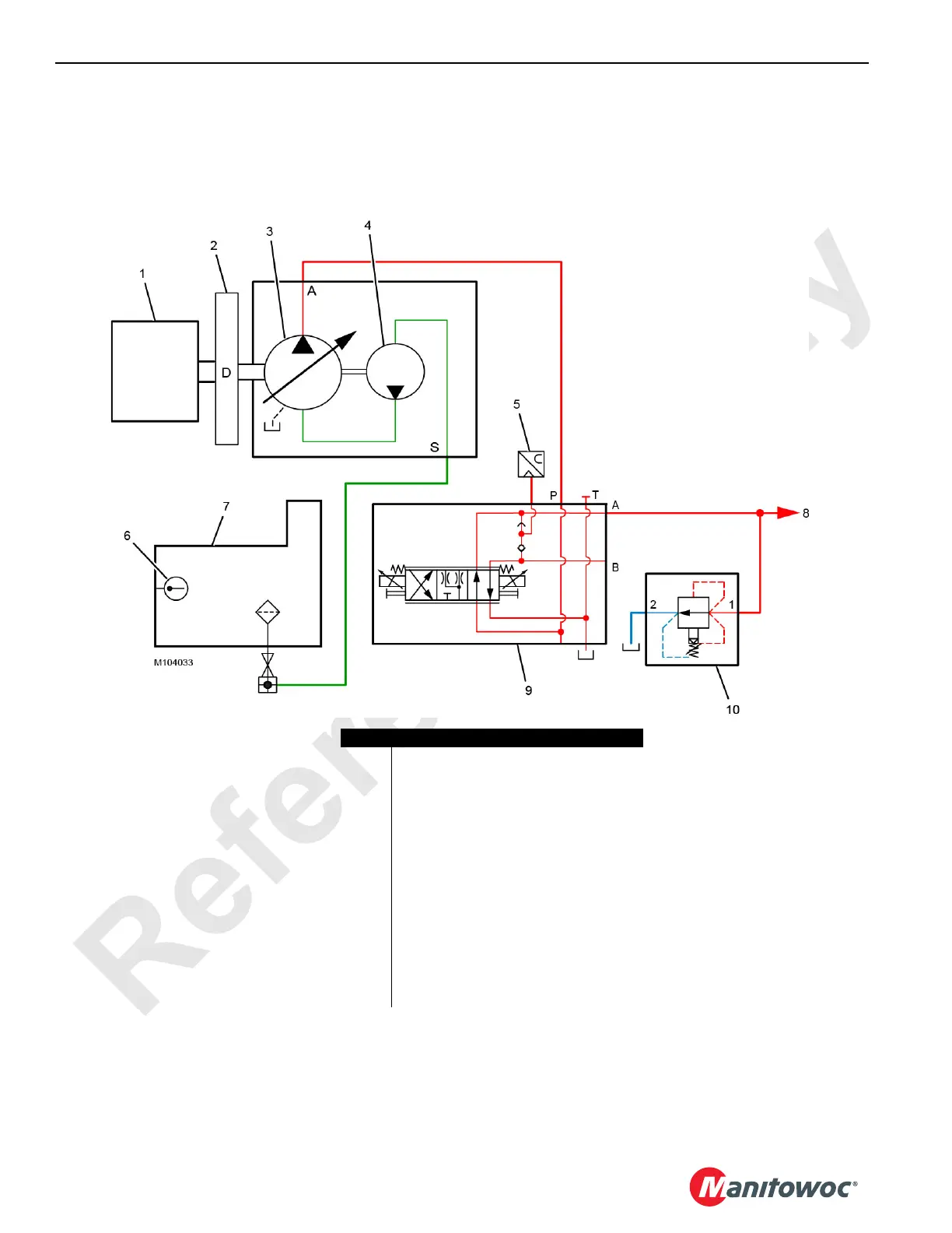
Warming Circuit Hydraulic Schematic
FIGURE 10-1
Item Description
1 Engine
2 Pump Drive (inboard pad D)
3 Hydraulic Main Pump 4
4 Charge Pump
5 Isolation A PSI Pressure Transducer
6 Temperature Sensor
7Hydraulic Tank
8 To Accessory Circuits:
• Live Mast Pin Pullers
• Gantry Equalizer Pin Pullers
• Live Mast Assist Arms
• Cab Tilt
9 Isolation Valve A (left side valve bank)
(also referred to as accessory valve)
10 Warming Relief Valve

 Loading...


