147
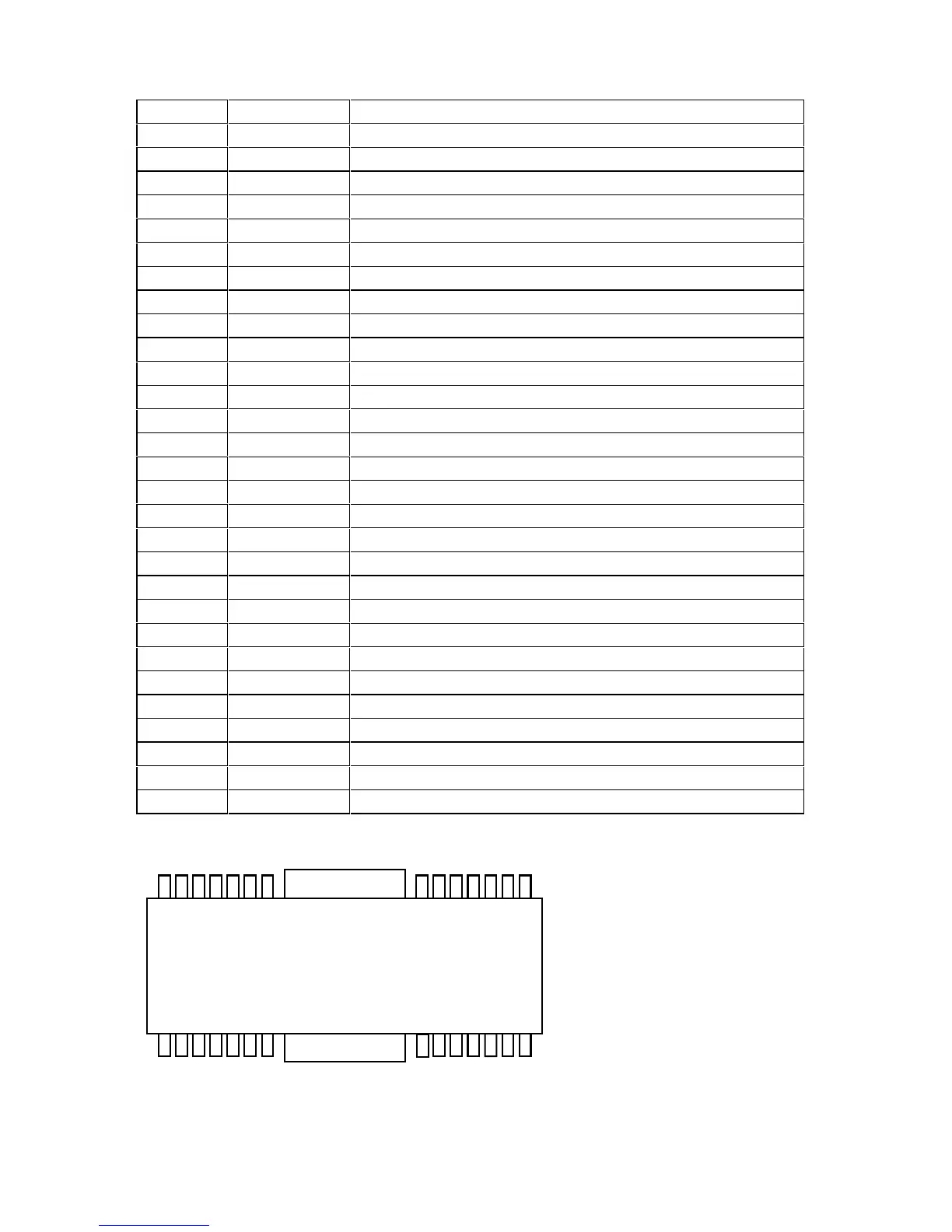
pin description
PIN No PIN NAME DESCRIPTION
1 N.C. Not connected
2 N.C. Not connected
3A
3
Output 3 for motor
4 N.C. Not connected
5A
2
Output 2 for motor
6 N.C. Not connected
7A
1
Output 1 for motor
8 GND Ground
9H
1
+
Hall input Amp1. positive input
10 H
1
-
Hall input Amp1. negative input
11 H
2
+
Hall input Amp2. positive input
12 H
2
-
Hall input Amp2. negative input
13 H
3
+
Hall input Amp3. positive input
14 H
3
-
Hall input Amp3. negative input
15 N.C. Not connected
16 FG3 FG3 signal output terminal
17 FG2 FG2 signal output terminal
18 FG1 FG1 signal output terminal
19 V
H
Hall Bias
20 C
NF
Capacitor connection pin for phase compensation
21 E
CR
Torque control standard voltage input terminal
22 E
C
Torque control voltage input terminal
23 PS POWER SAVE switch
24 R
EV
Reverse terminal
25 V
CC
Power supply for sinal division
26 V
M2
Power supply 2 for driver
27 V
M1
Power supply 2 for driver
28 R
NF
Power supply for driver division
FIN FIN GND
Terminal lay-out
V
M2
V
CC
R
EV
PS
E
C
E
CR
C
NF
V
H
FG1
FG2
N.C.
A
2
A
1
GND
H
1+
H
1-
H
2+
H
2-
R
NF
V
M1
FG3
N.C.
H
3+
H
3-
N.C.
N.C.
N.C.
A
3