26
5.5.5 Tests with diagnostic software program
The SACD diagnostic program is included in the SACD
application software. This program permits to test a lot of
functions of the PCB. We group in this part the memory tests,
the general serial bus tests and the peripheral tests of the
mono board.
Start up
Conditions
The units required are the SACD power supply, the mono
board and the DAC board. This is the minimum set up for the
diagnostic program, when testing memories and peripherals.
When using the Compair serial cable, pin 1602-2 is directly
connected to GND and after powering on, the diagnostic
program will be started.
The other end of the service cable is connected to a PC serial
port. On the PC you need to open an HyperTerminal and
configure it as follows: 19200 b/s, 8 bits data, no parity, 1 stop
bit, no control flow.
Start the diagnostic
When you switch on, the diagnostic checks the serial port in
both directions, followed by few other commands. Those are
done automatically during power up. The following message
is displayed on the HyperTerminal: "SACD1000 Diagnostic
Software version ...". Then the program is waiting that you
select a mode. Getting this screen means the Sti5505 can
boot from flash. The program is running and the service
interface is functioning. Enter the mode you wish to use. You
can use either the Menu mode or the Command mode. In the
first mode, the main menu appears, you can navigate into the
menu system and you can select the individual command,
just type the corresponding number to launch it. In the
second mode, just type the Ref.# number to do the test.
When a Ref.# command is available in the diagnostic
program, it will be explained as follow :
At the end of the test, the diagnostic program will return “OK”
if the test is passed. Otherwise an error message will appear.
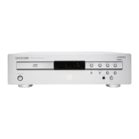
System clock
ST_CLK is the system clock and is derived from the 27 MHz
by the internal PLL of the Sti5505 (pin137).
Memories
Flashes
Read flash test:
If you can start the diagnostic that means you are able to read
the flashes and the program is running. Then you can
normally use the diagnostic program. At this moment you can
launch the checksum calculation from the diagnostic
program.
If you don’t encounter any problem during utilisation of the
diagnostic program means the Sti5505 is properly connected
to the flashes.
SDRAM
Use the diagnostic program for a complete software test of
the SDRAM.
I2C bus test
EEprom
To access the EEPROM, the I2C bus is used. So writing and
reading back to the EEPROM check the chip and the bus.
The complete EEPROM can also be checked but it takes a
lot of time to write and read back at all the locations.
Display board
The mono board accesses to the display board through the
I2C bus. You can test this serial bus up to the connector
1501. So connect the display board to the mono board and
launch either the following command :
Ref.# Command Name Remark
Name Test point Frequency Level
ST_CLK F822 49.95 MHz TTL
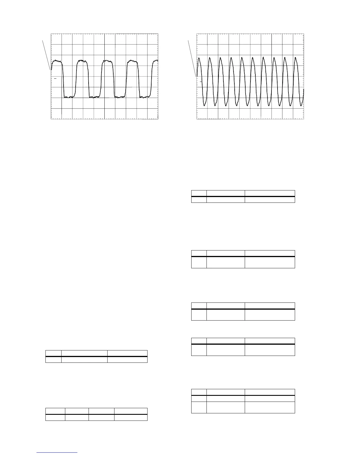
PM3394B
ch1
ch1: freq= 8.50MHz
CH1 1.00 V~ MTB50.0ns ch1+
1
MACE CLK
CL 06532152_020.eps
051200
Ref.# Command Name Remark
100 Checksum FLASH
Ref.# Command Name Remark
104 SDRAM Write
Read
Extensive test
Ref.# Command Name Remark
123 NVRAM I2C Quick test - Write and
read back
Ref.# Command Name Remark
122 NVRAM write read Extensive test - Write
and read-back
Ref.# Command Name Remark
500 Echo Write and read back
501 version Software version of the
slave processor rom
PM3394B
ch1
ch1: freq= 50.0MHz
CH1 1.00 V~ MTB20.0ns ch1+
1
ST_CLK
CL 06532152_021.eps
051200